Laser photo-thermo-acoustic (PTA) frequency swept heterodyned lock-in depth profilometry imaging system

a technology of laser photo-thermo-acoustic and depth profilometry, which is applied in the field of methodology and instrumentation development, can solve the problems of laser jitter noise, acoustic and thermal noise within the wide bandwidth of the transducer, and the inability to control the depth localization of contrast-generating sub-surface features, and limit the system detectivity and signal-to-noise ratio (snr)

Inactive Publication Date: 2005-10-20
MANDELIS ANDREAS +3
View PDF6 Cites 28 Cited by
  • Summary
  • Abstract
  • Description
  • Claims
  • Application Information

AI Technical Summary

Benefits of technology

[0037] The subject matter of the present invention consists of a novel technique for imaging of biological tissues based on frequency-sweep heterodyne detection, digital signal processing and image reconstruction algorithms, as well as the instrumental hardware configurations employed for acoustic wave generation and detection using photo-thermo-acoustic (PTA) phenomena. The novel PTA i

Problems solved by technology

Pulsed PTA detection, however, presents disadvantages in terms of laser jitter noise, acoustic and thermal noise within the wide bandwidth of the transducer, hard-to-control depth localization of the contrast-generating sub-surface features, as well as strong background signals from sound scattering tissues.
These mechanisms tend to limit system detectivity and signal-to-noise ratio (SNR) and amount to important limitations because they may seriously compromise the contributions to the signal of contrast-generating subsurface features and thus limit the ability to monitor nascent and small size tumors by the PTA technique.
In addition, very large pulsed-laser peak fluences incident on living tissue may have detrim

Method used


Image

  • Laser photo-thermo-acoustic (PTA) frequency swept heterodyned lock-in depth profilometry imaging system
  • Laser photo-thermo-acoustic (PTA) frequency swept heterodyned lock-in depth profilometry imaging system
  • Laser photo-thermo-acoustic (PTA) frequency swept heterodyned lock-in depth profilometry imaging system

Examples


Embodiment Construction

Apparatus

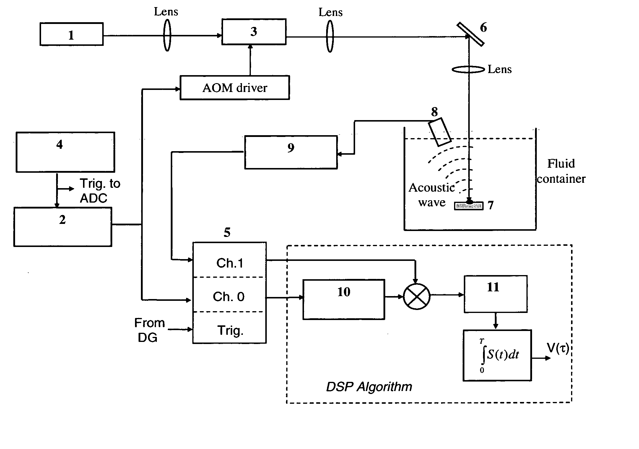
[0054] One embodiment of the frequency-sweep heterodyne PTA imaging system is shown in FIG. 5. The laser used to generate PTA pressure waves is an Ytterbium fiber laser (IPG Photonics, 1064 nm) 1. A frequency-swept (chirp) signal is generated by a function generator (FG, Stanford Research Systems, DS345) 2 to drive the acousto-optic modulator (AOM, Neos Technologies, N15180-1.06-Gap) 3 and modulate the intensity of the laser beam. The chirp signal of FG is triggered by a delay-pulse generator (Stanford Research Systems, DG 535) 4, which is also used to trigger the high-speed analog-to-digital converter (ADC) board (National Instruments, PXI-5122) 5. The laser beam is reflected using an optical mirror 6 and focused onto the specimen 7. A commercial acoustic transducer (Panametrics, V382) 8 is used to detect the acoustical signal. The received signal is amplified by a preamplifier (Panametrics, 5676) 9 and is fed into channel 1 of the ADC board 5. Input channel 0 of the ADC...


PUM


Abstract

A method and apparatus for biomedical subsurface imaging and measurement of thickness, elastic and optical properties of industrial and biomedical materials based on laser Photo-Thermo-Acoustic (PTA) frequency-swept heterodyne depth profilometry, In particular, the invention relates to biomedical imaging and measure of tissue and tumour thickness, L, speed of sound, cs, acoustic attenuation coefficient, γ, optical absorption coefficient, μa, and optical scattering coefficient, μs. The method and apparatus involves providing for a sample of the material to be characterized; irradiating the material for a selected period of time with an excitation waveform from a modulated optical excitation source wherein a photo-thermo-acoustic emission is responsively emitted from said solid; detecting said emitted photo-thermo-acoustic emission; processing the electronic signal to convert the frequency-domain signal into time-domain and perform depth profilometric imaging and determining thermoelastic and optical properties of the material sample;

Description

[0001] We claim the benefit of the priority date Feb. 17, 2004 as per provisional patent application No. 60544969.TECHNICAL FIELD [0002] The present invention relates to methodology and instrumentation development, in laser Photo-Thermo-Acoustic (PTA) frequency-swept heterodyne depth profilometry, for biomedical subsurface imaging and measurement of thickness, elastic and optical properties of industrial and biomedical materials. In particular, the invention relates to biomedical imaging and measurement of tissue and tumour thickness, L, speed of sound, cs, acoustic attenuation coefficient, γ, optical absorption coefficient, μa, and optical scattering coefficient, μs. BACKGROUND OF INVENTION [0003] The photoacoustic (PA), or more precisely, the photo-thermo-acoustic (PTA) effect is the process of light being absorbed by a material, creating a temperature change followed by a localized volume expansion leading to the generation of acoustic waves. In addition to obvious applications i...

Claims


Application Information

Patent Timeline
IPC IPC(8): A61B5/05G01B21/08G01N21/17G01N21/47G01N29/06G01N29/07G01N29/11G01N29/46
CPCG01B21/085G01N21/1702G01N21/4795G01N29/0609G01N2291/0421G01N29/11G01N29/46G01N2291/02475G01N2291/02872G01N29/07
Inventor MANDELIS, ANDREASVITKIN, ALEXTELENKOV, SERGEYFAN, YING
Owner MANDELIS ANDREAS
Why Eureka
Try Eureka