
Skin grafting devices and methods

a skin grafting and device technology, applied in the field of skin grafting, can solve the problems of increasing the cost of the procedure, affecting the effect of the procedure, and the device is expensive, so as to improve the ease, speed and reproducibility of the procedur

Active Publication Date: 2005-10-20
KCI LICENSING INC
View PDF6 Cites 127 Cited by
  • Summary
  • Abstract
  • Description
  • Claims
  • Application Information

AI Technical Summary

Benefits of technology

[0018] Devices and methods are provided for enhancing the ease, speed and reproducibility of harvesting, processing, and applying skin particles prepared from STSG, and further wherein such application may be combined with negative pressure therapy. The term “wound” as used in the context of the present invention, may include, but is not limited to, bums, incisional wounds, excisional wounds, ulcers, traumatic wounds, and chronic open wounds.
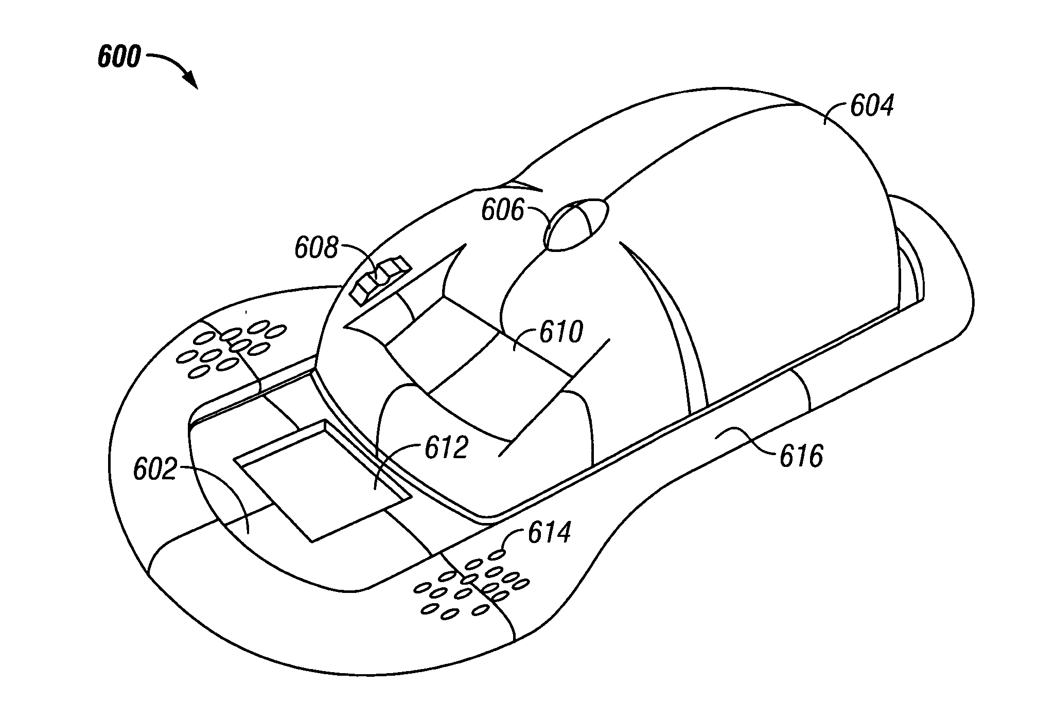
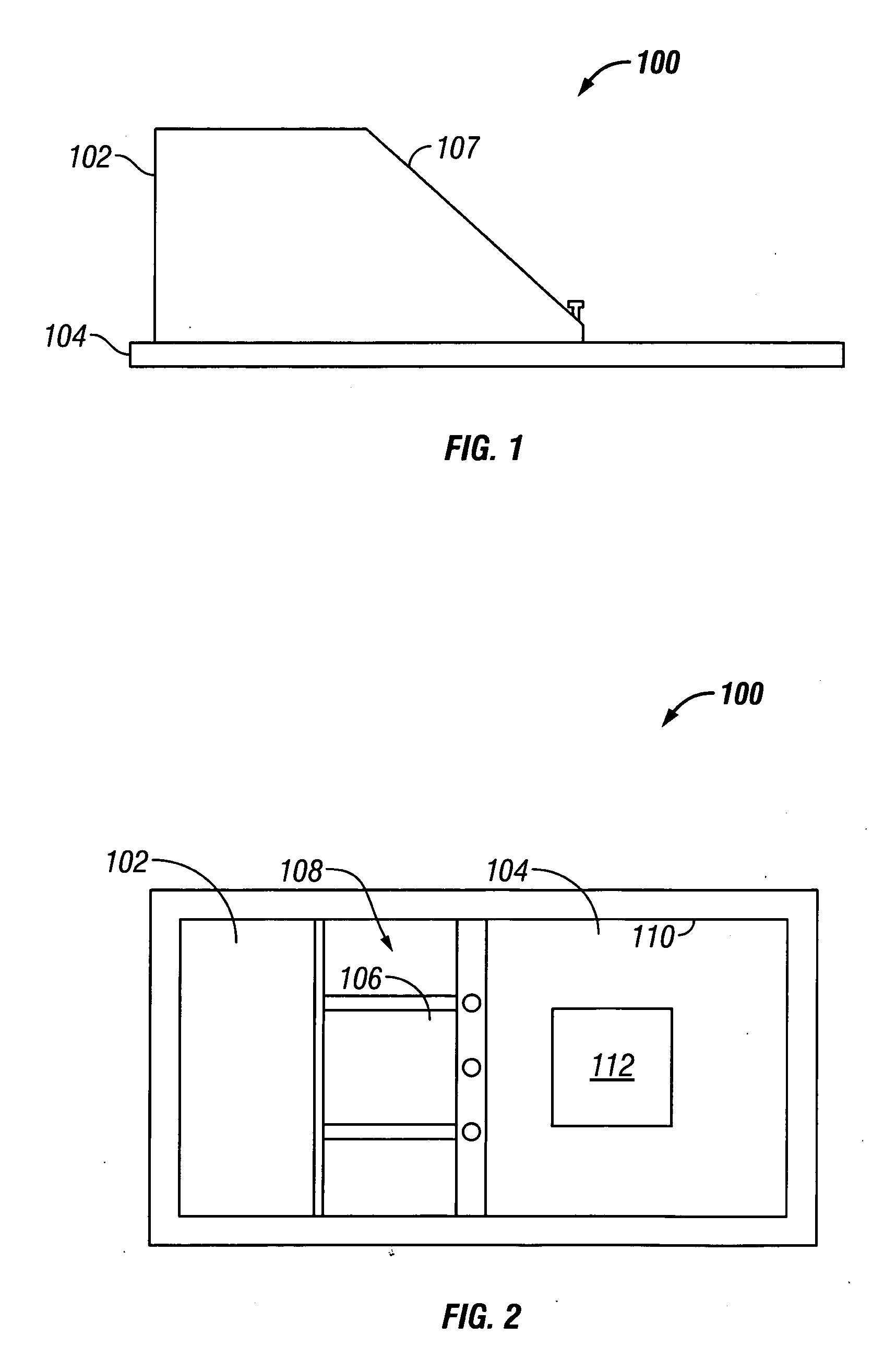
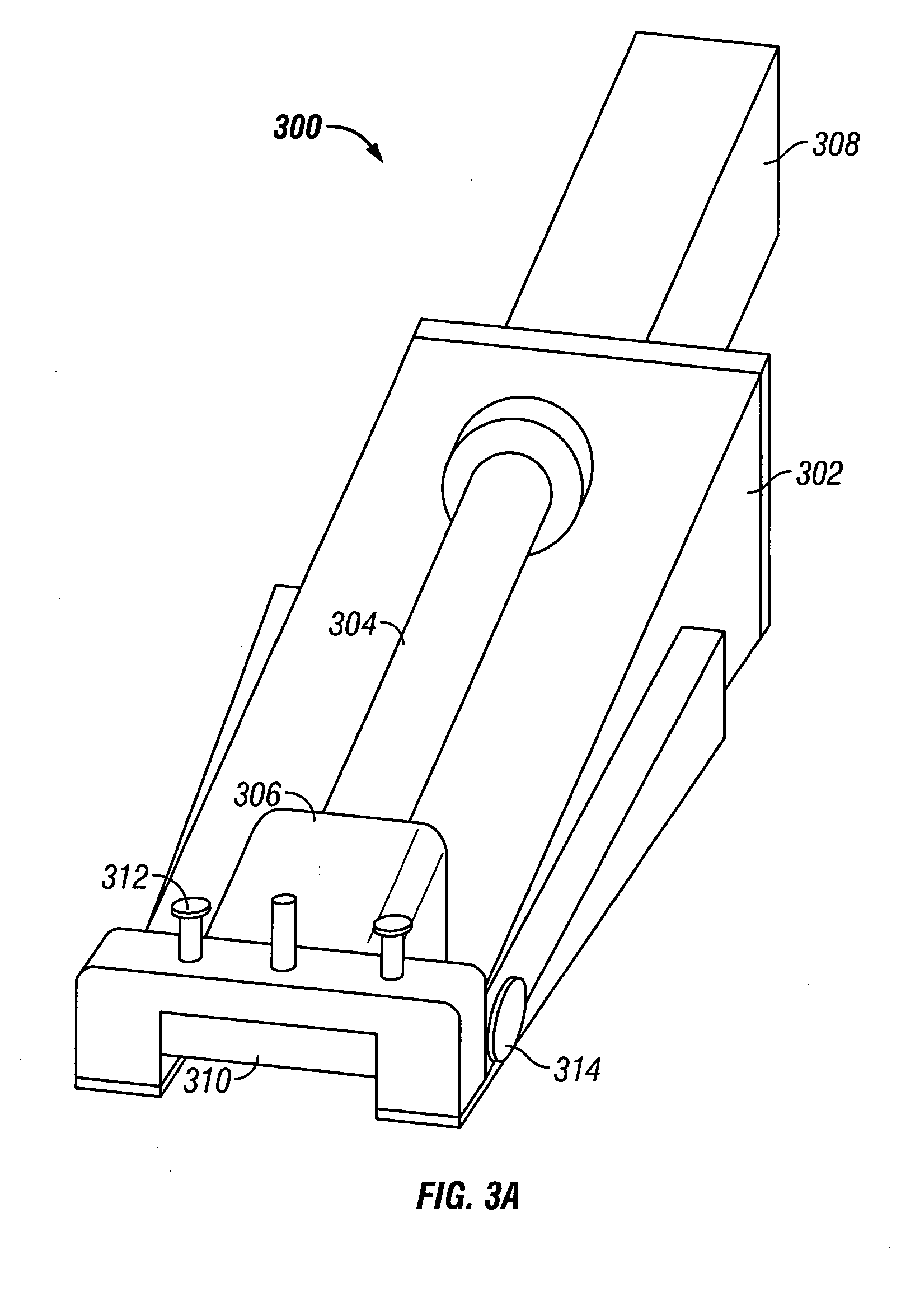
[0020] One aspect of the present invention is a skin-harvesting device that is comparatively easily operable compared to hand held dermatomes and that removes a sufficient amount of skin at a substantially consistent thickness and dimension during use.
[0023] In some embodiments, the angle of the blade in the blade housing is adapted to be fixed relative to the window to eliminate any variation in tissue harvesting caused by changes in the blade angle. In typical embodiments, the device is adapted to be disposable after a predetermined number of uses. In some embodiments, batteries are provided to power the motor, and the device is adapted to be used on a single patient (single patient use). In further embodiments, the cutting frame is adapted to move freely along the tracks of the base dependent on directional changes by the user.
[0029] These features described above together eliminate the main components of user variability and thus allow a uniform split thickness graft to be obtained by less skilled and less experiences users than known in the art. Alignment with a mincing device is also included, to allow the graft to be processed into small particle sizes.

Problems solved by technology

The skin grafting techniques have many wonderful benefits, but are still replete with a number of problems.
Each of these steps interposes various challenges and obstacles, e.g., technical, therapeutic and financial, in executing a successful graft.
These devices are expensive and the operation is known to be highly dependent on user skill and training, and requires involved procedures to accurately obtain a successful harvest.
As a result, these devices are primarily wielded only by experienced plastic surgeons.
Use of these dermatomes are generally confided to the operating room setting, increasing the cost of the procedure, especially given the average fee for operating room use.
Apart from minimizing trauma incurred at the donor site, a major factor limiting survival following extensive injury is insufficient availability of donor sites to provide enough skin for the required grafting procedures.
While greater ratios than 9:1 may be possible using meshing techniques, there is a concomitant significant delay in epithelization with using such ratios.
However, disadvantages of using pieces larger than 1500 μm have been noted.
For example, in skin pieces of this size cells remote from a cut edge have a limited availability to migrate and proliferate and thereby contribute to forming new skin.
In addition, the techniques employed have required each piece to be oriented epidermis upwards, making the procedure tedious and impractical.
Further, the appearance of the new skin that is produced using particles of this size is poor, often having a cobblestone appearance.
Current methods of distributing micrografts, such as mechanical spreading results in clumps or aggregates of skin particles, frustrating an even distribution.
Such particles cannot readily integrate with the wound bed and also will have a reduced potential for nourishment from the wound fluid exudates and consequently have an decreased potential to remain viable.
Thus, the aggregation of micrografts reduces the efficiency of epithelization and may significantly increase the time required to close a wound.
Despite being highly successful in the promotion of wound closure and healing many wounds previously thought largely untreatable, some challenges remain with the use of negative pressure therapy.
If cellular tissue has grown excessively into the dressing, there is the potential that dressing changes without due care and attention may result in some tissue damage at the wound site.
The problem of frequent dressing changes would likewise tend to frustrate the combination of micrografts with negative pressure treatment, in that the dressing change may remove or displace micrografts.

Method used


Image

  • Skin grafting devices and methods
  • Skin grafting devices and methods
  • Skin grafting devices and methods

Examples


example 1

Aggregation of Nanografts on a Wound Site when Distributed by Mechanical Spreading

[0177] STSG harvesting and wound preparation were performed on anesthetized pigs. STSGs were harvested using a commercially available Padgett Dermatome at a nominal depth setting of 0.013 inch (335 μm). They were subsequently minced to 600 μm nanograft particles using a skin mincing device wherein the operation was performed in 2 steps, or cuts. The first cut produced strips of tissue parallel to each other. These strips were then rotated 90 degrees and cut a second time with the parallel blade mincing device to produce cubes from the STSG.

[0178] The nanografts were mechanically spread onto a wound site at an expansion ratio of 6:1. As shown in FIG. 28, the mechanical spreading results in clumps of skin particles that are interspersed with areas that have little or no coverage by the nanografts. Characteristic clumps are exemplified in the inset image as indicated by the arrows.

example 2

Vacuum Assisted Dispersion of Nanografts onto a Nylon Mesh

[0179] STSG harvesting was performed on anesthetized pigs. STSGs were harvested using a commercially available Padgett Dermatome at a nominal depth setting of 0.013 inch (335 μm). They were subsequently minced to 600 μm nanograft particles using a skin mincing device wherein the operation was performed in 2 steps, or cuts. The first cut produced strips of tissue parallel to each other. These strips were then rotated 90 degrees and cut a second time with the parallel blade mincing device to produce cubes from the STSG. The nanografts were stained purple with crystal violet for ease of viewing and suspended in saline.

[0180] A nylon mesh was placed into a vacuum reservoir and a particle restraint device was inserted to confine settlement of particles to an area of diameter of 2.5 inches (same diameter as test wound in Example 3). The suspension of nanografts was placed into the interior of the restraint device and vacuum was a...

example 3

Effect of Nanograft Size on Outgrowth Materials & Methods

[0181] STSG harvesting and mincing for this study were performed on live, anaesthetized pigs with visual proliferation studies starting ˜24 hours after harvest. Minced STSG specimens were plated in 6-well (35 mm diameter) collagen coated plates (biocoat, Becton Dickinson) at expansion ratios of ˜6:1. STSGs were harvested using a commercially available Padgett Dermatome at a nominal depth setting of 0.014 inch (355 μm). They were subsequently minced to 300 μm×300 μm, 600 μm×600 μm and 1000 μm×1000 μm squares using a skin mincing device wherein the operation was performed in 2 steps, or cuts. The first cut produced strips of tissue parallel to each other. These strips were then rotated 90 degrees and cut a second time with the parallel blade mincing device to produce cubes of STSG of various dimensions. The spacing between the blades was varied to vary the size of the cubes.

[0182] In the time between harvest and plating, sampl...


PUM


Abstract

The present invention provides skin grafting and devices that comprise a systematic approach to the process of skin grafting, i.e., harvesting, post-excision processing and application of donor skin and pre and post-graft treatment of the recipient site.

Description

CROSS-REFERENCE TO RELATED APPLICATIONS [0001] This application claims priority to U.S. Provisional Application Ser. No. 60 / 537,108, filed 14 Jul. 2004, and to U.S. Provisional Application Ser. No. 60 / 629,001 filed 18 Nov. 2004. This application is also a continuation-in-part of co-pending U.S. patent application Ser. No. 10 / 075,743 filed 14 Feb. 2002 that claims the benefit of U.S. Provisional Application Ser. No. 60 / 269,956, filed 16 Feb. 2001, and a continuation-in-part of co-pending U.S. patent application Ser. No. 10 / 379,342 filed 3 Mar. 2003. The entire text of each of the above-referenced disclosures is specifically incorporated by reference herein without disclaimer.BACKGROUND OF THE INVENTION [0002] 1. Field of the Invention [0003] The present invention relates generally to skin grafting and related devices and methods. The present invention provides a systematic approach to the process of skin grafting, i.e., harvesting, post-excision processing and application of donor sk...

Claims


Application Information

Patent Timeline
IPC IPC(8): A61B17/32A61B17/322
CPCA61B17/322A61M1/0052A61M27/00A61M1/0088A61M1/784A61M1/90A61M1/98A61B2017/320064
Inventor SEEGERT, CHARLESJOHNSON, ROYCE W.BOCCUTI, A. DAVIDGENTILE, ANDREW NICHOLASGRIFFEY, SYSANDERS, TERYL BLANE
Owner KCI LICENSING INC
Learn More