Methods and apparatus for injecting atomized fluid

a technology of atomized fluid and method, which is applied in the direction of fuel injecting pumps, mechanical apparatus, machines/engines, etc., can solve the problems of affecting affecting the efficiency of atomizers, so as to reduce the emissions of oxides of nitrogen (nox) and enhance the performance of atomizers

Active Publication Date: 2005-10-27
TENNECO AUTOMOTIVE OPERATING CO INC
View PDF17 Cites 96 Cited by
  • Summary
  • Abstract
  • Description
  • Claims
  • Application Information

AI Technical Summary

Benefits of technology

[0011] The present invention provides improved methods and apparatus for injecting fluid, such as an aqueous urea solution, into an exhaust stream in order to reduce oxides of nit...

Problems solved by technology

Such engines are said to run “lean” or on a “lean mixture.” However, this increase in fuel economy is offset by undesired pollution emissions, specifically in the form of oxides of nitrogen (NOx).
However, use of such an aqueous urea solution involves many disadvantages.
Urea is highly corrosive and attacks mechanical components of the SCR system, such as the injectors used to inject the urea mixture into the exhaust gas stream.
Solidified urea may foul moving parts of the injector and clog any openings, rendering the injector unusable.
In addition, if the urea mixture is not finely atomized, urea deposits will form in the catalytic reactor, inhibiting the action of the catalyst and thereby reducing the SCR s...

Method used


Image

  • Methods and apparatus for injecting atomized fluid
  • Methods and apparatus for injecting atomized fluid
  • Methods and apparatus for injecting atomized fluid

Examples


Embodiment Construction

[0032] The ensuing detailed description provides exemplary embodiments only, and is not intended to limit the scope, applicability, or configuration of the invention. Rather, the ensuing detailed description of the exemplary embodiments will provide those skilled in the art with an enabling description for implementing an example embodiment of the invention. It should be understood that various changes may be made in the function and arrangement of elements without departing from the spirit and scope of the invention as set forth in the appended claims.

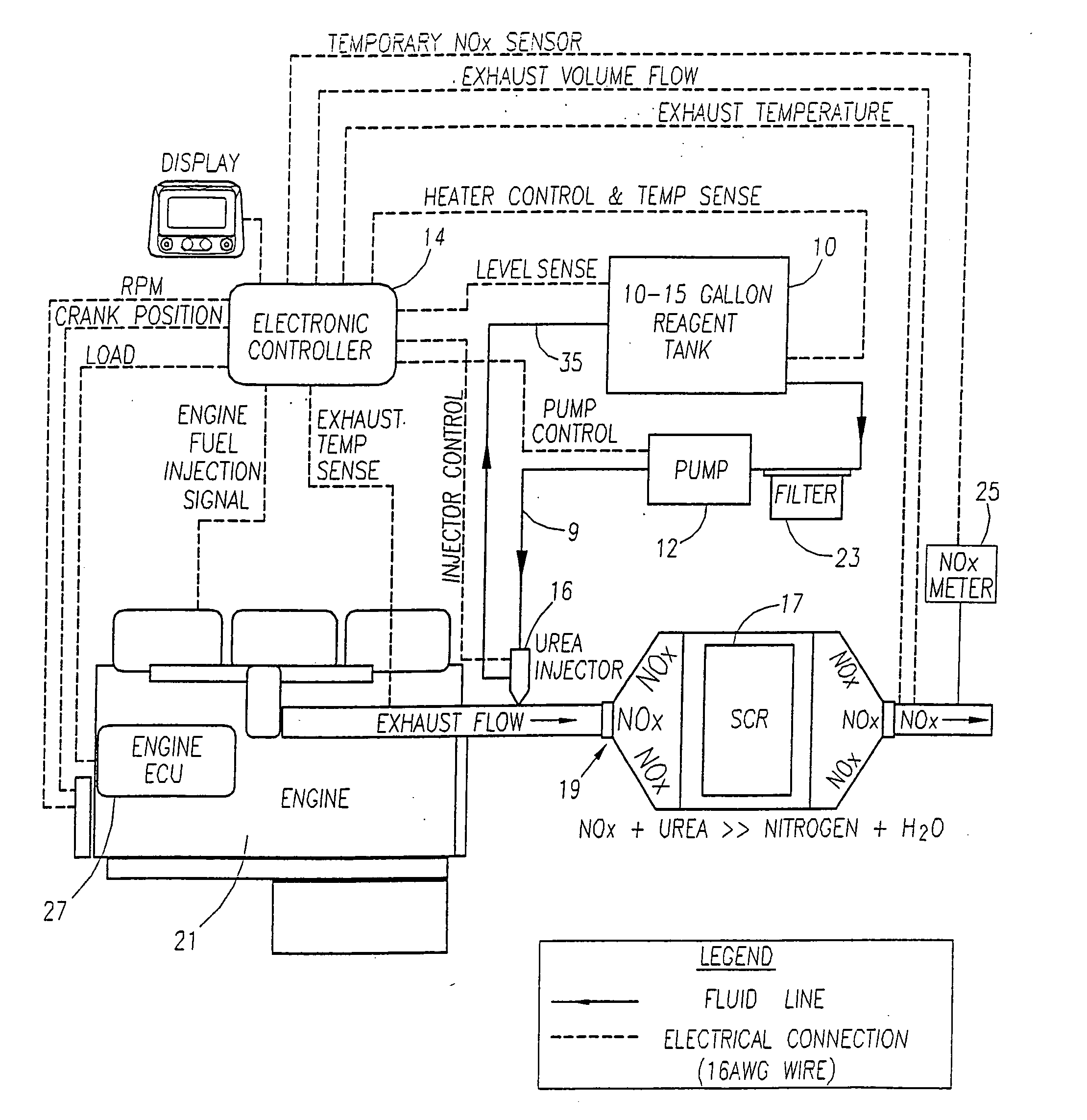
[0033]FIG. 1 shows an example pollution control system for reducing NOx emissions from the exhaust of a diesel engine 21. In FIG. 1, solid lines between the elements of the system denote fluid lines and dashed lines denote electrical connections. The system of the present invention may include reagent tank 10 for holding the reagent (e.g., aqueous urea) and a delivery module 12 for delivering the reagent from the tank 10. The tank 10...


PUM


Abstract

The present invention provides methods and apparatus for injecting fluid, such as an aqueous urea solution, into an exhaust stream in order to reduce oxides of nitrogen (NOx) emissions from diesel engine exhaust The present invention uses mechanical spill return atomization techniques to produce droplets approximately 50 μm SMD (Sauter mean diameter) or smaller. This size range is appropriate to allow urea to react into ammonia within the residence time associated with an on-road diesel engine. This effect is achieved through the use of a whirl plate having a plurality of whirl slots surrounding an exit orifice of the injector, which produce a high velocity rotating flow in the whirl chamber. When the rotating flow of fluid is passed through the exit orifice into an exhaust stream, atomization occurs from a combination of centrifugal force and shearing of the fluid by air as it jets into the exhaust stream.

Description

[0001] This application claims the benefit of U.S. Provisional Application No. 60 / 565,356, filed Apr. 26, 2004.BACKGROUND OF THE INVENTION [0002] The present invention relates generally to the reduction of emissions produced by lean burn engines. In particular, the present invention provides methods and apparatus for injecting fluid, such as an aqueous urea solution, into an exhaust stream in order to reduce oxides of nitrogen (NOx) emissions from diesel engine exhaust. [0003] Lean burn engines provide improved fuel efficiency by operating with an excess of oxygen over the amount necessary for complete combustion of the fuel. Such engines are said to run “lean” or on a “lean mixture.” However, this increase in fuel economy is offset by undesired pollution emissions, specifically in the form of oxides of nitrogen (NOx). [0004] One method used to reduce NOx emissions from lean burn internal combustion engines is known as selective catalytic reduction (SCR). SCR, when used, for example...

Claims


Application Information

Patent Timeline
IPC IPC(8): F01N3/00F01N3/20F01N9/00F02M51/00
CPCF01N3/2066Y02T10/24F01N2560/026F01N2560/06F01N2560/07F01N2610/02F01N2610/03F01N2610/11F01N2610/1453F01N2610/146F01N2900/08F01N2900/1808F01N2900/1811F01N2900/1814F02M53/04F02M53/08F02M61/162F01N3/208Y02T10/12
Inventor TARABULSKI, THEODORE J.SANTANGELI, P. ROBERTBRODERICK, R. GIFFORD
Owner TENNECO AUTOMOTIVE OPERATING CO INC
Why Eureka
Try Eureka