
Method to improve the quality of dispersion formulations

a technology of dispersion formulation and quality improvement, which is applied in the field of high-speed material design workflow, can solve the problems of pigment dispersions, color discoloration of inks, further problems related with heterogeneous systems, etc., and achieve the effects of accelerating research, reducing production costs, and reducing production costs

Inactive Publication Date: 2005-10-27
AGFA NV
View PDF14 Cites 62 Cited by
  • Summary
  • Abstract
  • Description
  • Claims
  • Application Information

AI Technical Summary

Benefits of technology

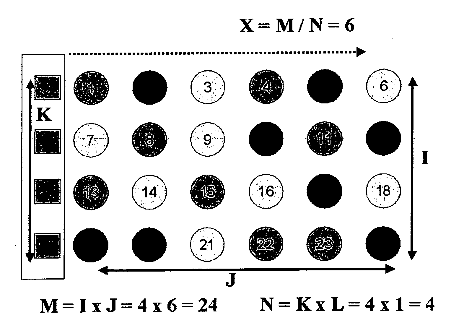
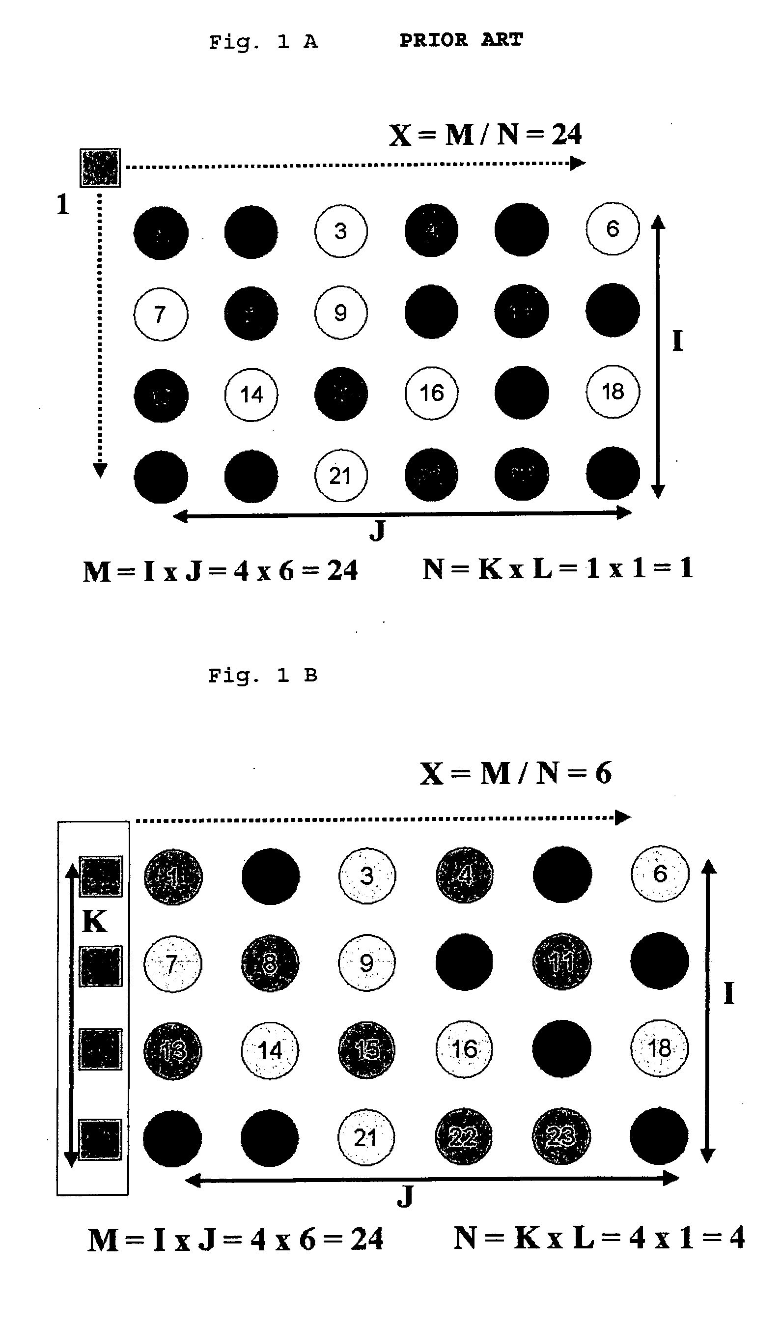
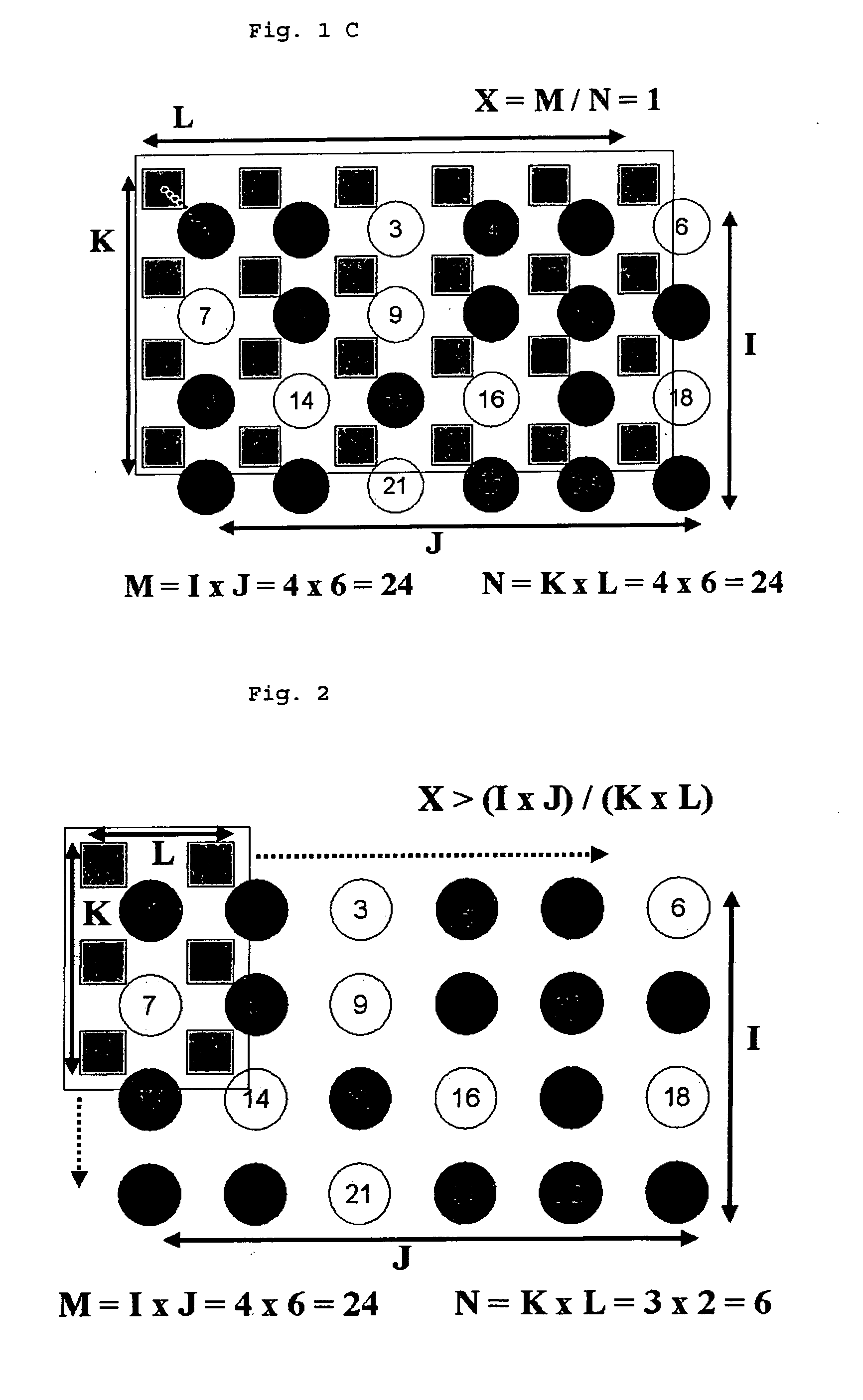
[0015] It is further an ever lasting object to develop a faster method than hitherto available, preferably on smaller scales than ever applied, in order to consume smaller amounts of material, not only without reducing the number of said experiments, but opposite thereto even increase said number of experiments in order to improve research efforts and to accelerate research: as more formulations are envisaged to be prepared and screened in less time on a smaller scale, it is a further object to decrease the cost per sample to a large extent.

Problems solved by technology

Conventional grinding media however have been found to be unacceptable because they either increase the pH of the dispersion to an unacceptable level, resulting in inks having incompatibility with ink processing and printing equipment or result in contamination of the dispersion, thereby leading to discoloration of inks prepared from the above-described pigment dispersions.
Particle size and distribution depend on a variety of parameters like the type of mill or the crushing parts (e.g. silica) and the need to remove the crushing parts after milling, that leads to further problems related with heterogeneous systems.
An alternative to start from the molecular solution and to form particles by precipitation results in problems related to crystal growth by Ostwald ripening and / or particle agglomeration, further resulting in sedimentation and / or flotation.
Said dispersion synthesis method however provides no information about dispersion quality factors obtained thereby.
From our own experience, when making inks having the final composition as envisaged, those inks comprise particle agglomerates in a medium of polymeric stabilizers and additives, but said inks are unacceptable for practical use, due to coarse agglomerates.
The “dispersion process” normally involves addition of e.g. zirconium oxide pearls and an overnight roller bench step, but this treatment step imposes considerable drawbacks as explained earlier.
Whereas in all of those applications serial dispersion preparation methods have been described, it is clear that these processes, predominantly based on application of shear forces, are time-consuming, in part due to the large scale on which the experiments are performed, and that high speed preparation of well-dispersed complex dispersions is not easy: normally the composition is prepared, followed by a sequential “dispersing” step so that the speed of material design is very slow.

Method used


Image

  • Method to improve the quality of dispersion formulations
  • Method to improve the quality of dispersion formulations
  • Method to improve the quality of dispersion formulations

Examples


examples

[0134] While the present invention will hereinafter be described in connection with preferred embodiments thereof, it will be understood that it is not intended to limit the invention to those embodiments.

[0135] While ultrasonic or ultraturrax techniques were performed, all dispersions were kept at a temperature of 15° C., unless otherwise specified in the description of the examples hereinafter.

[0136] In a first experiment ink-jet ink dispersions were prepared by weighing 600 mg of pigment powder on an Autodose Powdernium® MTM solid handler into small glass test tubes having an outer diameter of 13 mm and an height of 75 mm.

[0137] The rack with tubes was then moved to an Anachem SK233 liquid handler to add an amount as tabulated in Table 1 of a stock solution of a polymeric dispersant and distilled water. Dosing on the SK233 was done in volumetric mode.

[0138] After magnetic stirring on a 60-position Variomag stirrer for 30 minutes, the test tubes were further used in a next dis...

examples 1-6

1-5; INVentive EXamples 1-6:

[0139] In a first experiment said set of inks was measured without dispersion improvement treatment and after an improvement treatment on a Tomtec Autogizer equiped with individual Sonics® probes of maximum 130 Watt and a 6 mm diameter probe tip. The device was operated in a fast serial way, with as main variation the duration of the ultrasonic treatment. After the dispersion improvement treatment the resulting dispersion was diluted by a factor of about 5000 (depending on the extinction coefficient of the colorant). This was done on the SK233 liquid handler in 2 or 3 separate steps in order to obtain a high dilution accuracy (e.g. 700 μl of the MK8490 in 34.3 ml distilled water, and then again 400 μl of this diluted dispersion into 34.6 ml of distilled water). An absorption spectrum of this diluted dispersion was recorded on a Shimadzu 3401PC UV-VIS NIR spectrophotometer and the absorption intensity was measured at 615 nm and 830 nm. The ratio of these a...

examples 7-9

[0141] The same ink as in example 1 was used, but instead of an ultrasonic treatment on the Tomtec Autogizer, the robot was equiped with high speed homogenizers (Ultraturrax, high speed cutters) and the inks of the examples were treated as described in Table 3. After the dispersion improvement treatment the dispersion quality factors were determined as described for example 1.

TABLE 3ExampleInkDispersion TreatmentDQFCOMP 1I_1None3.8INV EX 7I_1 9 min. UT at 60% on TOMTEC11INV EX 8I_150 min. UT at 30% on TOMTEC10INV EX 9I_130 min. UT at 60% on TOMTEC12

[0142] It is clear that the dispersion improvement step, based upon a rapid parallel / serial high speed cutting principle yields better dispersions than without a dispersion improvement step, while small amounts of chemicals have been used and an efficient workflow can be followed.


PUM

PropertyMeasurementUnit
temperatureaaaaaaaaaa
particle size diameteraaaaaaaaaa
volumeaaaaaaaaaa

Abstract

In a combinatorial method of making and testing an array of nanoparticle formulations comprising the steps of making multi-compositional formulations; improving the dispersion quality of these formulations by high speed parallel homogenizing; rapid serial, semi-parallel or parallel characterising said formulations, said step of high speed parallel homogenizing proceeds by providing energy to said dispersion via an array of tips, wherein said energy is ultrasonic energy or high shear mixing energy.

Description

FIELD OF THE INVENTION [0001] The present invention is related to a workflow for high speed material design, more particularly to the development of ink-jet inks in an array of nanoparticular dispersion formulations, and to a workflow for making, improving and screening or characterising said array in order to control critical properties thereof. BACKGROUND OF THE INVENTION [0002] As disclosed in EP-A 0 878 516 pigment based inks are typically prepared by dispersing pigment agglomerates, formed when individual pigment particles cluster together in a dispersant. The size of the pigment agglomerates may be reduced by grinding the pigment dispersion using conventional grinding media such as glass, stainless steel, or zirconium oxide. Conventional grinding media however have been found to be unacceptable because they either increase the pH of the dispersion to an unacceptable level, resulting in inks having incompatibility with ink processing and printing equipment or result in contamin...

Claims


Application Information

Patent Timeline
Patent Type & Authority Applications(United States)
IPC IPC(8): B01J19/00C09B67/46C09B67/50C40B60/14G01N11/00
CPCB01J19/0046B01J2219/00308B01J2219/00315B01J2219/00481C40B60/14B01J2219/00691B01J2219/00702B01J2219/00756C09B67/0091B01J2219/00486
Inventor DESIE, GUIDOVANMAELE, LUCDEROOVER, GEERT
Owner AGFA NV
Learn More