Device for processing welding wire

Inactive Publication Date: 2005-10-27
LINCOLN GLOBAL INC
View PDF13 Cites 81 Cited by
  • Summary
  • Abstract
  • Description
  • Claims
  • Application Information

AI Technical Summary

Benefits of technology

[0004] In accordance with the broadest aspect of the invention, a welding wire traveling along a given path passes through a conductive contact tip into an elongated annular chamber or tunnel surrounded by a dielectric barrier of ceramic or glass. By surrounding the dielectric barrier with a conductive sleeve or ring and providing a high voltage, high frequency signal between the conductive tip and the conductive ring, a cold plasma is created around the ring by a phenomenon known as dielectric barrier discharge plasma. This cold plasma is generated by passing the high voltage, high frequency signal from the outer conductive ring to the wire through the dielectric barrier. The plasma in the annular chamber cleans the metal wire, after which the plasma and wire both exit from the chamber into the atmosphere. In this manner, a cleaning gas introduced adjacent the conductive tip moves with the wire and constitutes the gas forming the plasma. The gas in the form of a cold plasma is exhausted from the chamber together with the wire moving through the annular plasma chamber. The frequency of the power source is generally above 500 Hz and preferably above 18 kHz. Typically, the frequency is approximately 200 kHz. The applied voltage is 1000 volts and is preferably greater than 2.0 kV. Typically, the voltage is approximately 8.0 kV. The annular gap between the dielectric sleeve and the wire has a width of approximately 0.2-3.0 cm. The pressure of the processing or cleaning gas is sufficient to cause the plasma to exit the far end of the cleaning tunnel or chamber. A variety of power sources can be used to obtain the high voltage, high frequency signal necessary to create the dielect

Problems solved by technology

The plasma discharge become more uniform at higher frequency but the cost of the extremely high frequency power sour

Method used


Image

  • Device for processing welding wire
  • Device for processing welding wire
  • Device for processing welding wire

Examples


Embodiment Construction

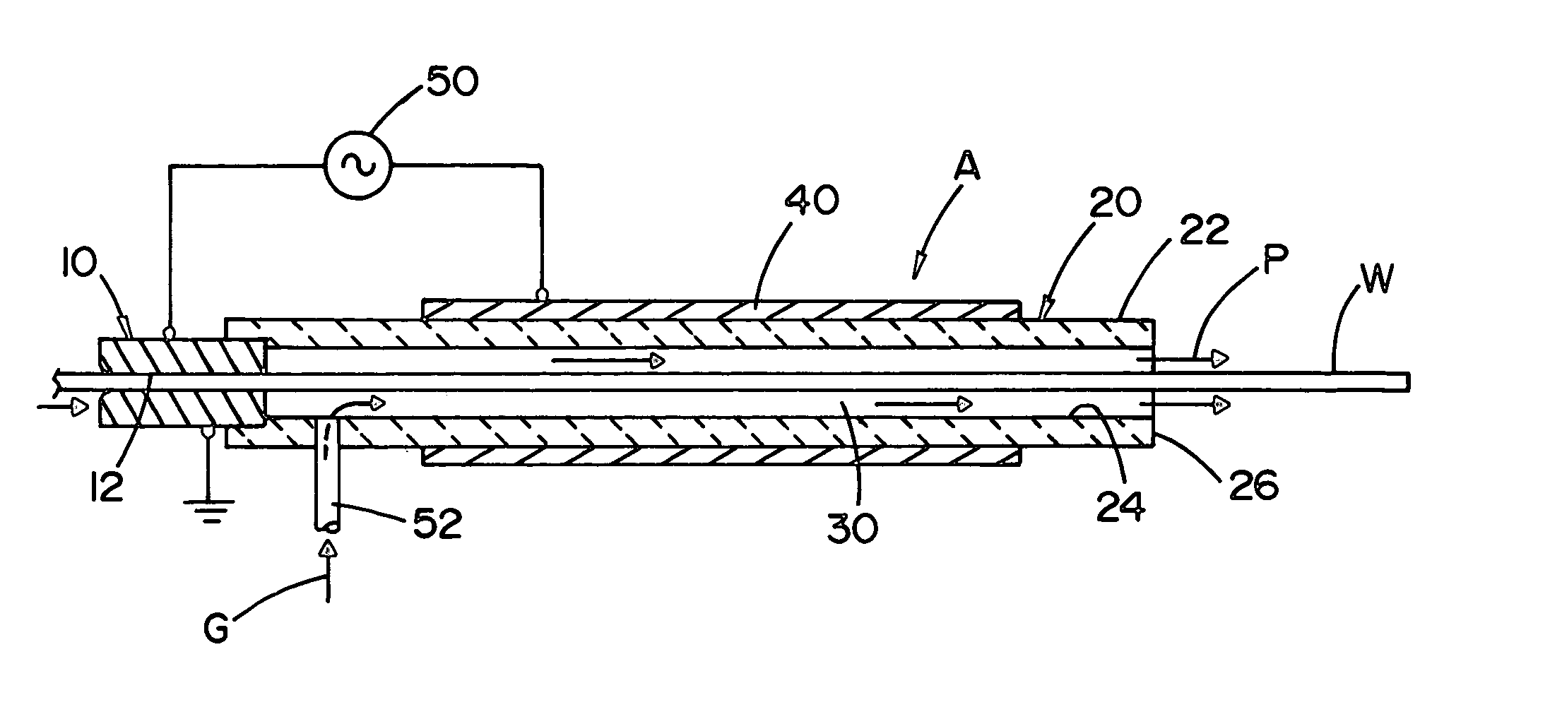
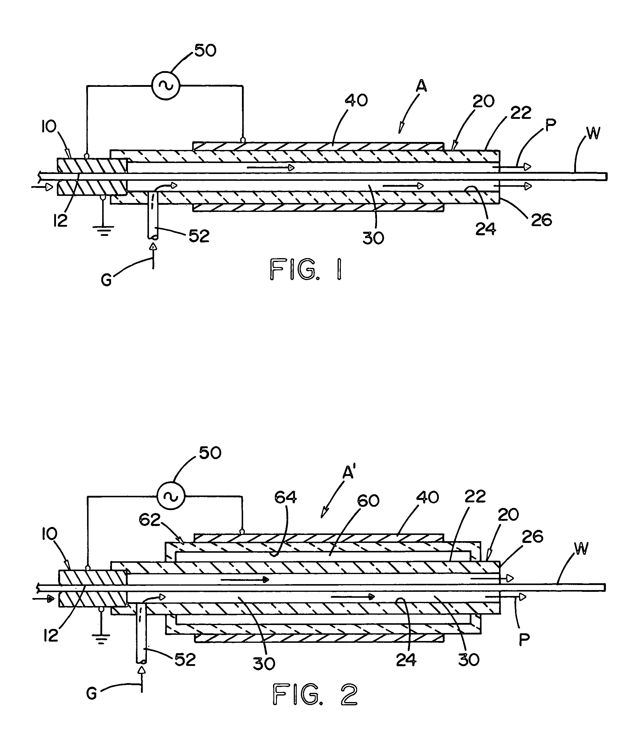
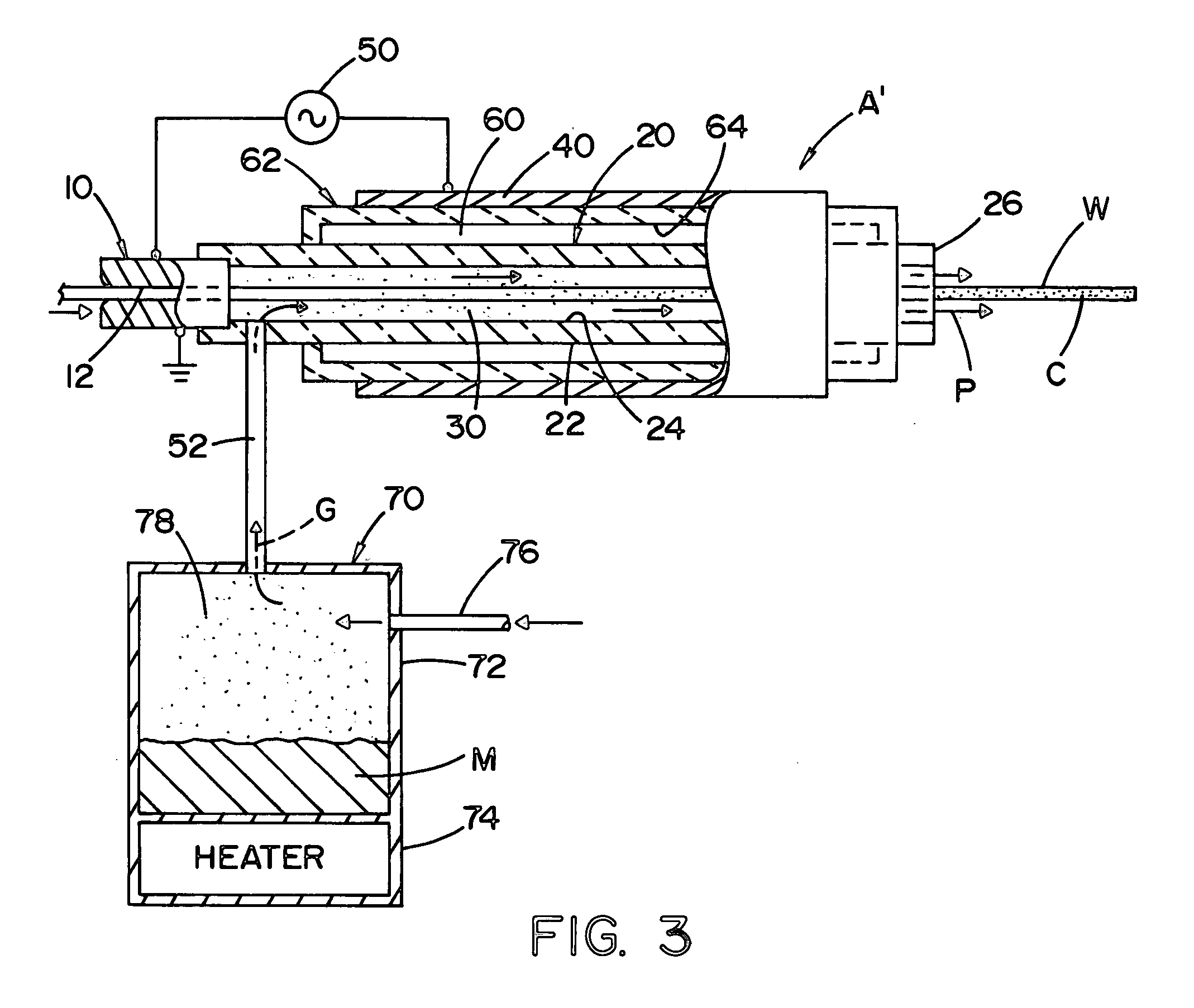
[0037] Referring now to the drawings wherein the showings are for the purpose of illustrating preferred embodiments only and not for the purpose of limiting same, FIG. 1 illustrates a device or tunnel A for processing a moving wire W, preferably in the form of a welding wire, either solid or cored, as the wire issues from a wire manufacturing line. The description of the invention and its details described in the introductory portion of this description are incorporated again by reference herein. Tunnel or device A includes a grounded contact tube 10 having a central passage or bore 12 through which wire W moves as it travels in a horizontal pass shown in FIG. 1. Contact tube 10 provides electrical contact with the moving wire and has, at its outlet end, a dielectric sleeve 20 with a general length of 1-3 meters. Sleeve 20 includes an outer cylindrical surface 22 and an inner cylindrical surface 24 spaced from wire W to define a wire passage or annular gap 30 extending from tube 10 ...


PUM

PropertyMeasurementUnit
Lengthaaaaaaaaaa
Electric potential / voltageaaaaaaaaaa

Abstract

A device for processing a wire having an outer surface and moving along a given path in a give direction. The device comprises a conductive contact tube surrounding said path and electrically engageable with the wire as it moves along the path and through the tue and a dielectric sleeve adjacent the contact tube and extending in the given direction from the contact tube and around the path to define an annular gas passage between the dielectric sleeve ad the wire. An inlet for processing gas is adjacent the contact tube in and a conductive electrode sleeve is around the dielectric sleeve so a high frequency, high voltage signal between said electrode sleeve ad the contact tube creates a dielectric barrier discharge plasma of the progressing gas in the annular passage.

Description

[0001] The present invention relates to the manufacture of welding wire and more particularly to a device for performing a continuous operation on welding wire as it is moving from the manufacturing process preparatory to winding the wire on a storage spool or in a storage package, such as a drum or box. INCORPORATION BY REFERENCE [0002] In the manufacturing of electric welding wire, either a solid wire or a cored wire, the wire is processed by drawing dies that result in contaminants on the surface of the wire. The need for cleaning the welding wire and a continuous process of performing this manufacturing process by induction heating is disclosed in Stava U.S. Pat. No. 6,365,864 incorporated by reference as background information regarding processing of welding wire after it has been drawn to size. Furthermore, after the wire is cleaned, it is sometimes necessary or desirable to apply a thin coating of material on the moving wire to enhance subsequent feeding capabilities and arc ...

Claims


Application Information

Patent Timeline
IPC IPC(8): B23K15/00B23K35/40C23F4/00H05H1/24
CPCB23K35/40H05H1/24C23F4/00H05H1/2406H05H1/2465H05H1/2443
Inventor BLANKENSHIP, GEORGE D.
Owner LINCOLN GLOBAL INC
Why Eureka
Try Eureka