Vehicle rotating electric machine

a technology of electric machines and electric motors, which is applied in the direction of machines/engines, propulsion parts, electric generator control, etc., can solve the problems of reducing electrostatic capacity, deterioration such as an increase of internal resistors, and inability to mount the idling stop system in the high temperature environmen

Active Publication Date: 2005-10-27
HITACHI LTD
View PDF8 Cites 29 Cited by
  • Summary
  • Abstract
  • Description
  • Claims
  • Application Information

AI Technical Summary

Benefits of technology

[0011] The present invention provides a vehicle rotating electric machine that is capable of realizing that a power converter device is mounted on a rotating electric machine body by about the same built-structure as the conventional one.
[0012] In order to provide the vehicle rotating electric machine, the present invention improves the property of mounting the power converter device onto the rotating electric machine body. As one of specific solving means, the power control circuit is configured by connecting a plurality of the following series circuits in parallel, each of the series circuits includes a P-channel MOS semiconductor device disposed at a higher potential side and an N-channel MOS semiconductor device disposed at a lower potential side which are electrically connected in series.
[0014] According to the present invention, since the inverter device can be downsized, there can be realized the vehicle rotating electric machine in which the inverter device is mounted on the rotating electric machine body by the substantially about same size as that of the general vehicle alternator. As a result, even in the small vehicle having a limited mounted space, the idling stop function can be provided without remarkably changing the layout of the interior of an engine room.

Problems solved by technology

On the other hand, since the inverter device has a large number of electronic parts that are low in the durability at high temperature, it is necessary that the inverter device is separated and arranged at a position that avoids a high temperature environment in the vicinity of the engine.
For that reason, additional parts such as the inverter device and the electric cable that connects the inverter device and the motor are disposed within an engine room having a limited space, and the idling stop system cannot be mounted without changing the layout of the interior of the engine room.
However, the electrolytic capacitor is larger in the volume than other electronic parts, and has such a characteristic that the electrostatic capacity is reduced and the deterioration such as an increase of the internal resistor is liable to occur under the high temperature environment.
As a result, it is difficult to realize the inverter built-in alternator that requires the downsizing and the high-temperature durability in the inverter circuit that requires the electrolytic capacitor.
However, in the case where the respective circuits are made up of the individual parts, it is very difficult from the viewpoint of sizes to realize that those circuits are equipped in the inverter built-in alternator.

Method used


Image

  • Vehicle rotating electric machine
  • Vehicle rotating electric machine
  • Vehicle rotating electric machine

Examples


Embodiment Construction

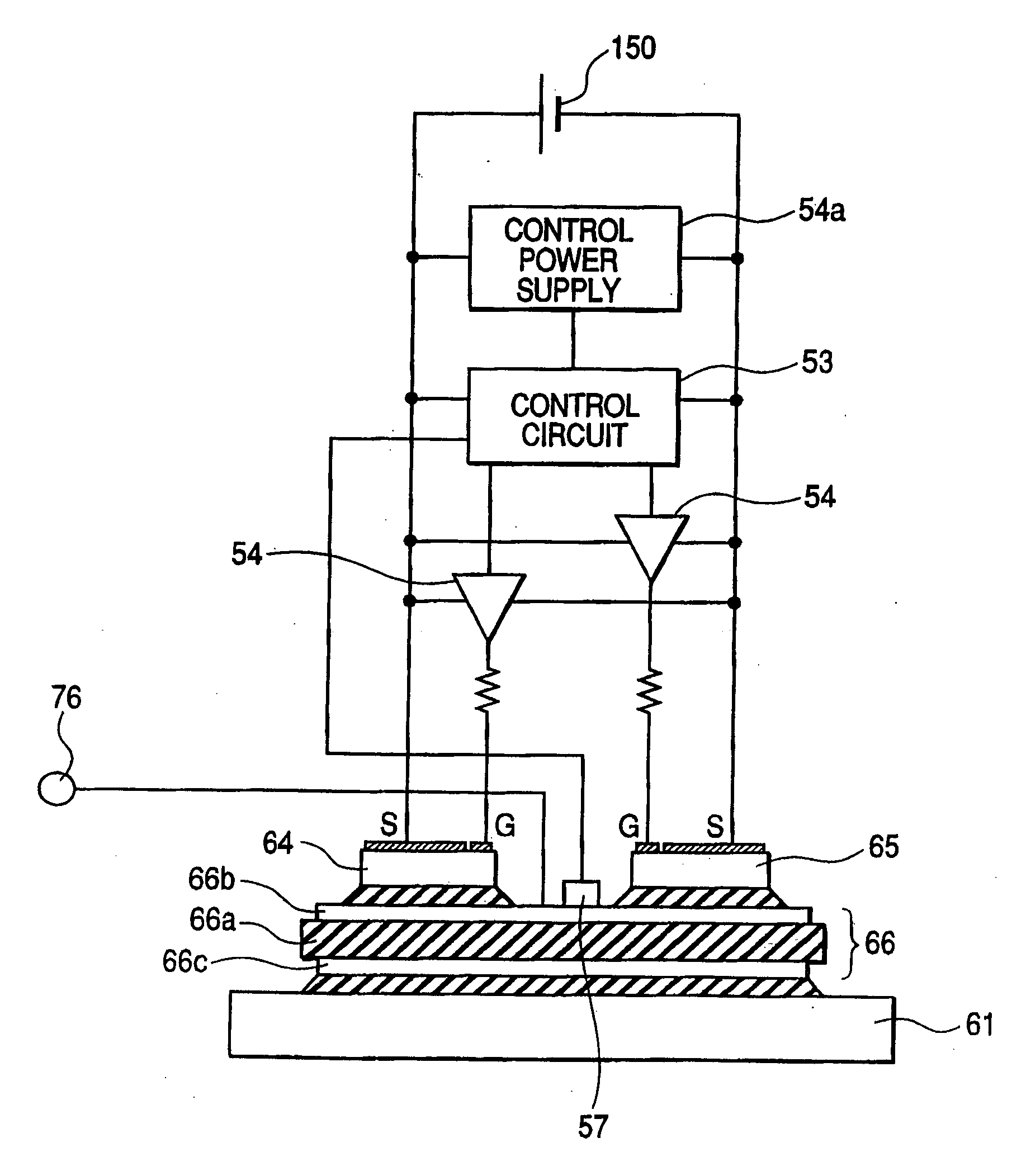
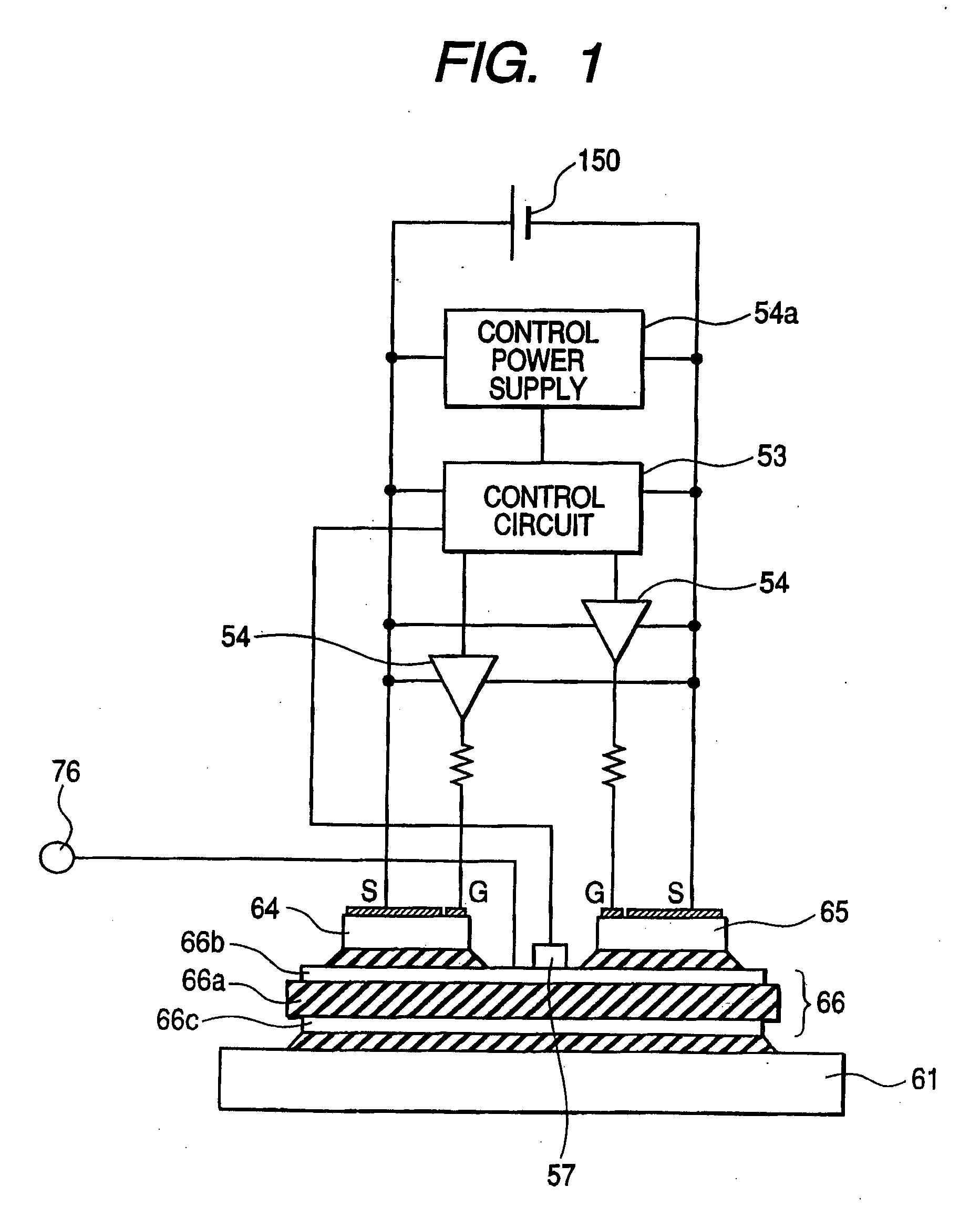
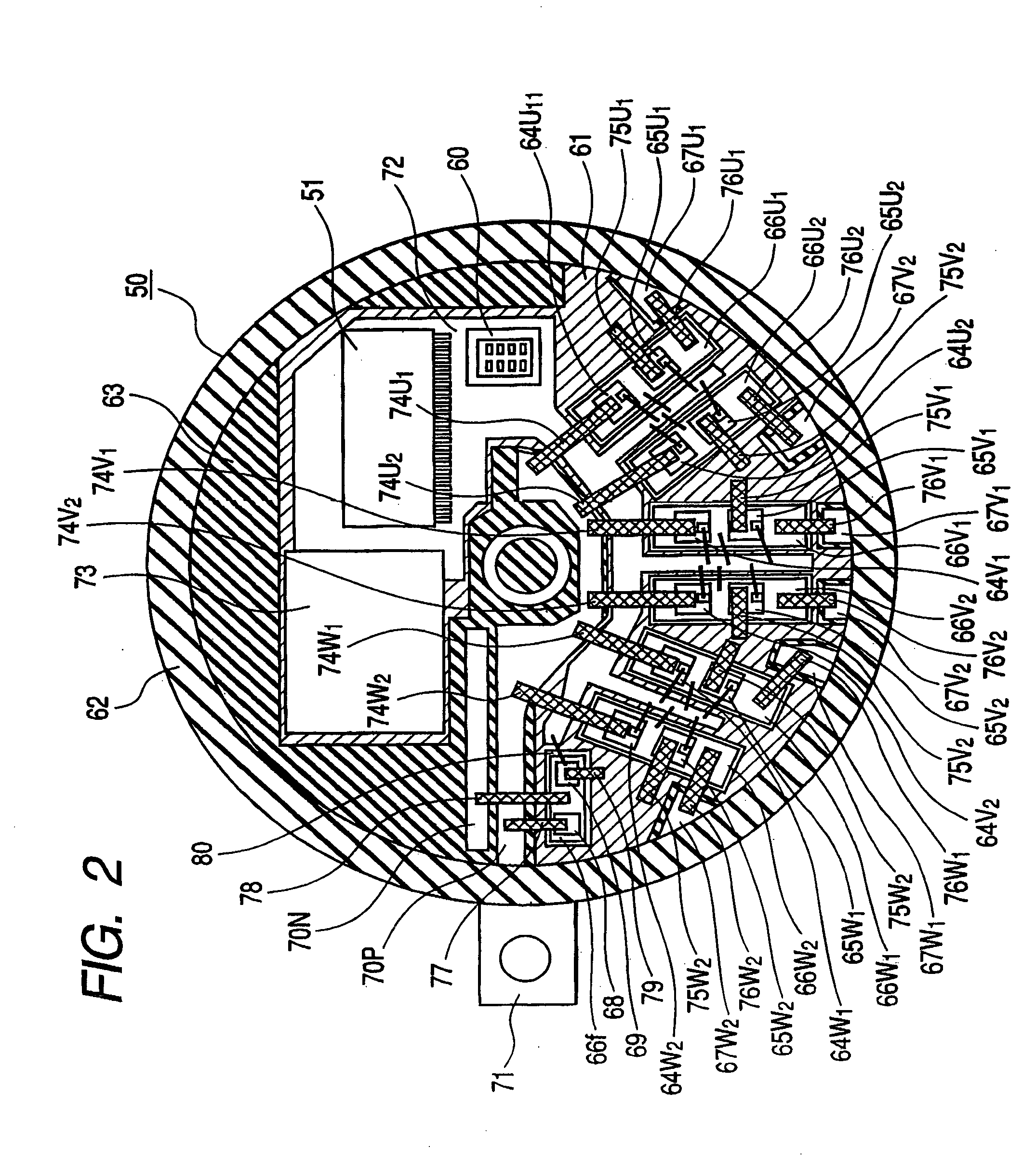
[0030] Hereinafter, embodiments of the present invention will be described with reference to FIGS. 1 to 11. A motor-alternator 100 according to an embodiment of the present invention is a so-called inverter built-in vehicle rotating electric machine in which an inverter device 50 is integrated with a rotating electric machine body 1, and constitutes an electric power train of an automobile 200.

[0031] The automobile 200 to which the motor-alternator 100 of the present invention is applied is a so-called hybrid automobile having both of an engine power train with an internal combustion engine as a power source and an electric power train with the motor-alternator 100 as a power source, as shown in FIG. 10. The engine power train is mainly used for a driving power source of the automobile 200. The electric power train is mainly used for the power source to make starting of the engine 120, and used for the electric power supply for the automobile 200. The automobile 200 having such an ...


PUM


Abstract

An inverter device is mounted on the rotating electric machine body The inverter device includes a module unit having a converter circuit and a control unit that controls the operation of the converter circuit. The converter circuit is configured by connecting a plurality of the following series circuits in parallel, each of the series circuits includes a P-channel MOS semiconductor device disposed at a higher potential side and an N-channel MOS semiconductor device disposed at a lower potential side which are electrically connected in series. An electric power that is supplied from a battery or an electric power that is supplied to the battery is controlled.

Description

CLAIM OF PRIORITTY [0001] The present application claims priority from Japanese application serial no. 2004-117027, filed on Apr. 12, 2004, and serial no. 2005-033760, filed on Feb. 10, 2005, the contents of which are hereby incorporated by references into this application. BACKGROUND OF THE INVENTION [0002] The present invention relates to a vehicle rotating electric machine to be mounted on a vehicle. [0003] For the purpose of improving fuel consumption and reducing an exhaust emission including carbon dioxide, in vehicles, there has been proposed an idling stop system for stopping an engine temporarily when the automobile are stopping such as waiting at a red light. The idling stop system provides an engine start system including, for example, a motor and an inverter device, separately from a starter. In this type, the motor is disposed in proximity to the engine, and transmits a driving force to the engine through a clutch and a belt at the time of restarting the engine. On the ...

Claims


Application Information

Patent Timeline
Patent Type & Authority Applications(United States)
IPC IPC(8): B60L9/18H02J7/14H02K11/00H02M7/5387
CPCB60K6/26B60K6/48B60W10/08F02D2041/2075F02N11/04Y02T10/7005F02N11/0859F02N2011/0896H02J7/1492H02M7/003Y02T10/6221F02N11/0814H01L2224/40225H01L24/40H01L2224/32225H01L2224/4103H01L24/41H01L2924/13091H01L2924/13055H01L2924/00014Y02T10/62Y02T10/70H01L2224/0603H01L2224/73221H01L2924/00H01L2224/37099H01L2224/84H01L24/36
Inventor SHIRAKAWA, SHINJIMORI, MUTSUHIROINABA, MASAMITSUYAMAUCHI, TATSUMIIWAMURA, MASAHIROMASHINO, KEIICHITSUCHIYA, MASANORI
Owner HITACHI LTD
Why Eureka
Try Eureka