Servo balancing among driver devices

a driver device and servo technology, applied in the field of amplifiers, can solve problems such as manifested amplifier outputs, and achieve the effect of improving the tracking accuracy of each servo amplifier

Inactive Publication Date: 2005-10-27
BIOURJA ENERGY SYST LLC
View PDF26 Cites 15 Cited by
  • Summary
  • Abstract
  • Description
  • Claims
  • Application Information

AI Technical Summary

Benefits of technology

[0020] In yet another embodiment, adjustment and calibration means are provided, to effect an improvement in the tracking accuracy of each servo amplifier associated with the slave amplifiers in a parallel array of amplifiers.

Problems solved by technology

Any imbalances among the amplifier outputs will be manifest as corresponding imbalances among the voltages appearing across the plurality of series resistors.

Method used


Image

  • Servo balancing among driver devices
  • Servo balancing among driver devices
  • Servo balancing among driver devices

Examples


third embodiment

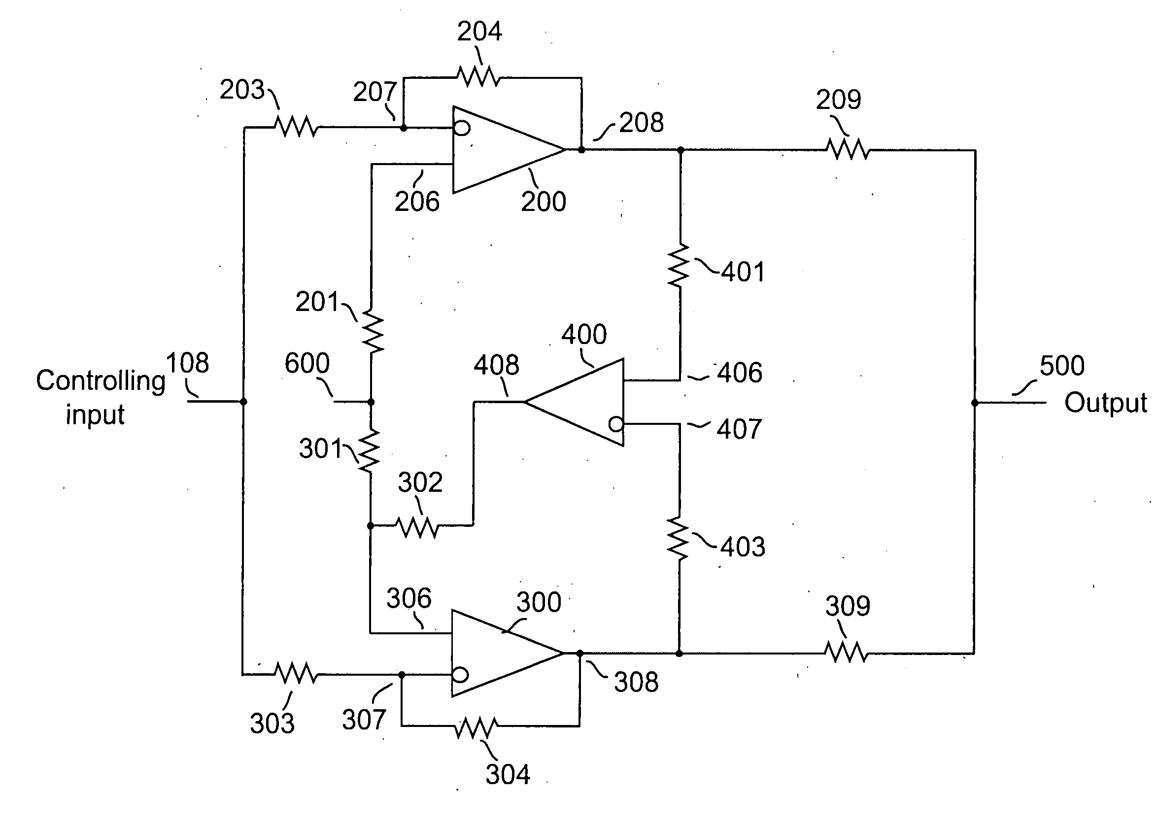
[0049] A third embodiment may be achieved by a slight alteration of the servo amplifier configuration disclosed above, whereby the servo feedback is applied to the inverting input of the associated slaved driver amplifier, as shown schematically for a pair of driver sections in FIG. 3. Note that when feedback is applied to the inverting input of the slave driver, the relative polarity of the servo amplifier's input connections must be reversed.

[0050] Amplifier 200 is operative as an inverting amplifier by virtue of the connection of the input control signal 108 through resistor 203 to inverting input 207 and the feedback to input 207 through resistor 204 from output 208. The gain of this section is determined in the conventional manner by the ratio of resistor 204 to resistor 203. Resistor 201 is optional, and may be included to ensure circuit stability. However, if stability is not an issue, a direct connection may be used in place of resistor 204 to reduce noise. Sense resistor 20...

fourth embodiment

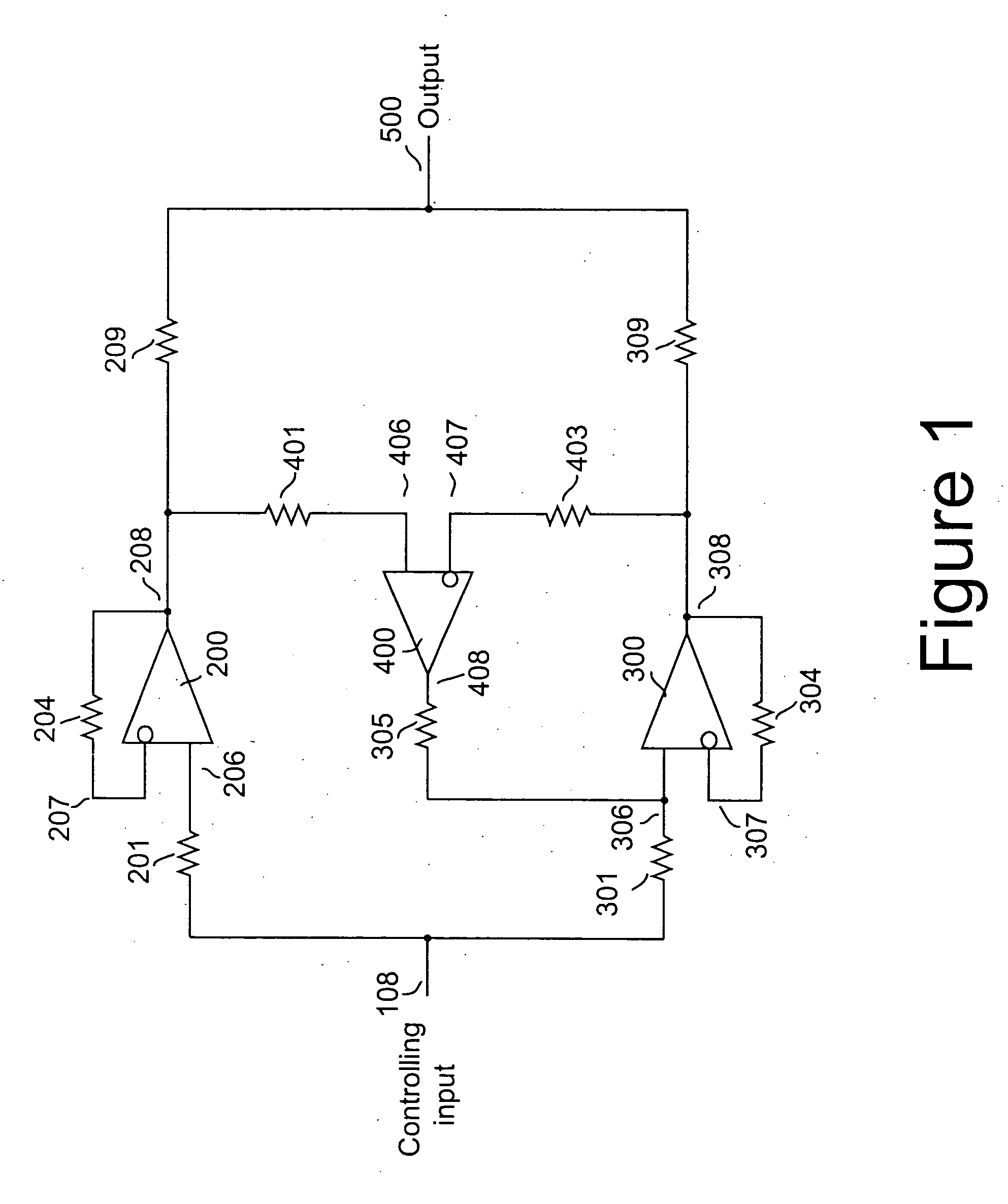
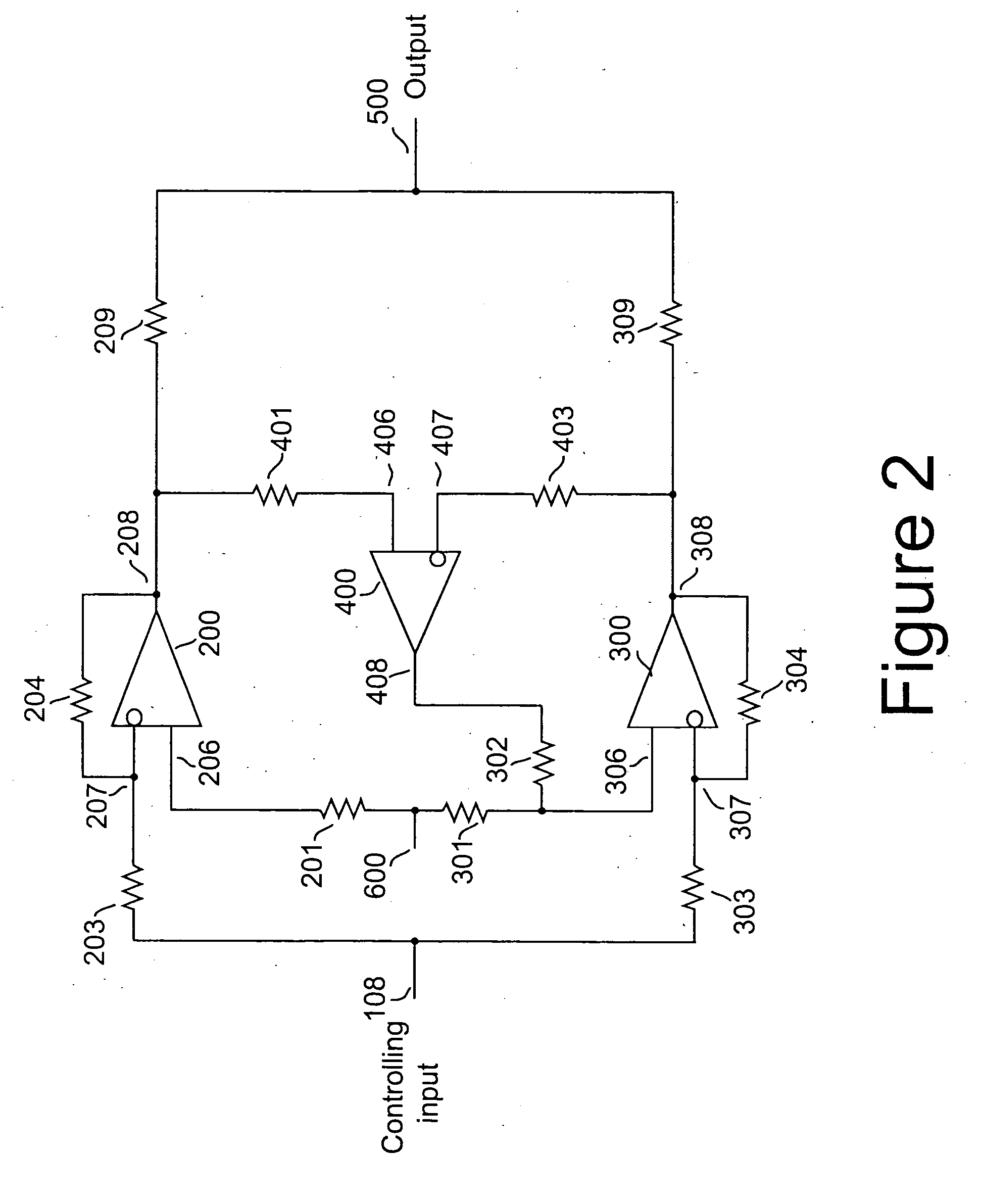
[0054] A fourth embodiment employs differential amplifiers configured to serve as non-inverting driver amplifiers. Servo feedback is applied to the inverting input of each slave, while the control input signals is applied to the non-inverting inputs of every driver amplifier, as shown schematically in FIG. 4 for a pair of drivers. Here again, when servo feedback is applied to the inverting input of the slave amplifier, the relative polarity of the associated servo amplifier's input connections must be reversed.

[0055] Amplifier 200 receives its controlling input from node 108, through resistor 201 connected to non-inverting input 206, and is operative as a non-inverting driver. Local feedback is conveyed from output 208 through resistor 204 to inverting node 207. Resistor 201 may be replaced with a direct connection if it is not needed to ensure stability. As is known in the art, the gain may be adjusted to a value greater than unity by adding a signal path between the inverting inpu...


PUM


Abstract

A method and apparatus for reducing imbalances among the outputs of a plurality of driver devices connected in a parallel configuration to drive a common load. One driver is designated as the master, and suitable servo circuitry is provided to each of the other slave drivers, each servo being operative to force the output of its associated slave driver to accurately track the output of the designated master driver. The servo circuitry may be disposed to equalize either the output voltages or output currents of the several drivers to ensure load balancing among the drivers, to reduce cross-conduction currents and attendant power wastage and improve dynamic performance. The plurality of drivers may either operate in an open-loop configuration, or be enclosed within an overall negative feedback loop under the control of a separate controller that itself may be an amplifier.

Description

FIELD OF THE INVENTION [0001] The present invention relates to amplifiers, and in particular, to a servo control method that ensures output balancing among amplifiers to both improve dynamic performance as well as increase efficiency by reducing cross-conduction losses, when a plurality of amplifiers are connected in a parallel arrangement to drive a common load. BACKGROUND OF THE INVENTION [0002] Whenever load currents in excess of a few milliamps are required to drive a load, two design approaches are available: either a single driver element may be used that is adequate to provide the required power, or several smaller driver elements may be deployed in a parallel arrangement such that each provides a substantially equal share of the drive power. As is known in the art, even nominally identical active devices will exhibit slightly different characteristics, so a means of ensuring accurate load balancing is almost always required whenever overall efficiency of a parallel array of ...

Claims


Application Information

Patent Timeline
Patent Type & Authority Applications(United States)
IPC IPC(8): H03F1/34H03F1/36H03F3/21H03F3/45H03F3/68
CPCH03F1/34H03F3/45475H03F3/211
Inventor LALETIN, WILLIAM H.
Owner BIOURJA ENERGY SYST LLC
Why Eureka
Try Eureka