Small footprint dual band dipole antennas for wireless networking

a dipole antenna and wireless networking technology, applied in the direction of antenna supports/mountings, resonant antennas, radiating element structural forms, etc., can solve the problems of large space occupation, less convenient use of access points and routers, and high cost, and achieve the effect of large manufacturing toleran

Inactive Publication Date: 2005-10-27
AMPHENOL T & M ANTENNAS
View PDF16 Cites 20 Cited by
  • Summary
  • Abstract
  • Description
  • Claims
  • Application Information

AI Technical Summary

Benefits of technology

[0009] An example embodiment prototype antenna exhibited a measured VSWR (voltage wave standing ratio) of 2:1 bandwidth in the 2.4 HGz band of 710 MHz. The measured VSWR 2:1 bandwidth in the 5 GHz band was wider than 1 GHz. The measured VSWR 3:1 bandwidth was more than 3.6 GHz, providing coverage from 2.32 GHz to more than 6 GHz. The dipole has 85%˜87% efficiency in 2.4 GHz band and 55˜64% efficiency in 5 GHz band. The range offered by the example embodiment (and by embodiments of the invention generally) provides a large manufacturing tolerance, making antennas of the invention practical for large scale fabrication.

Problems solved by technology

Multiple antennas can make access points and routers less convenient to use, more expensive, and more prone to fault.
Such antennas are suitable for low profile installations, but do not offer the good omni-directional coverage of dipole antennas.
This kind of printed dipole antenna design, however, occupies a relatively large space and the bandwidth in 5 GHz is limited.
However, the azimuth average gain in 2.4 GHz is low, around 0 dBi, which indicates a low efficiency.

Method used


Image

  • Small footprint dual band dipole antennas for wireless networking
  • Small footprint dual band dipole antennas for wireless networking
  • Small footprint dual band dipole antennas for wireless networking

Examples


Embodiment Construction

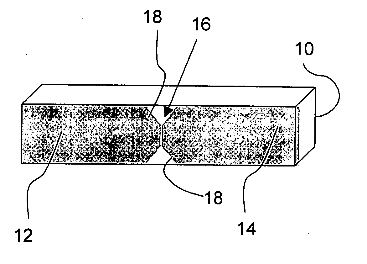
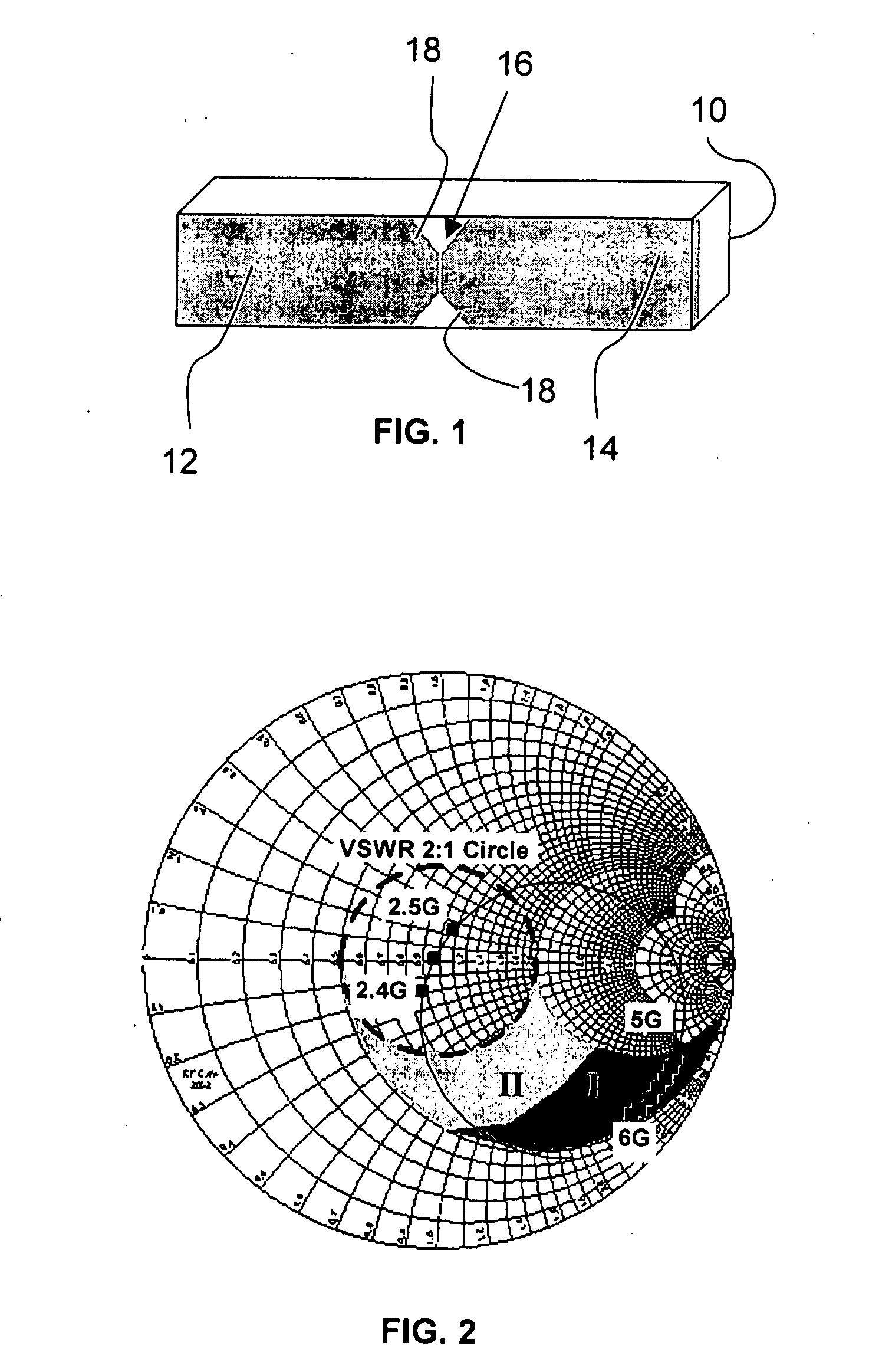
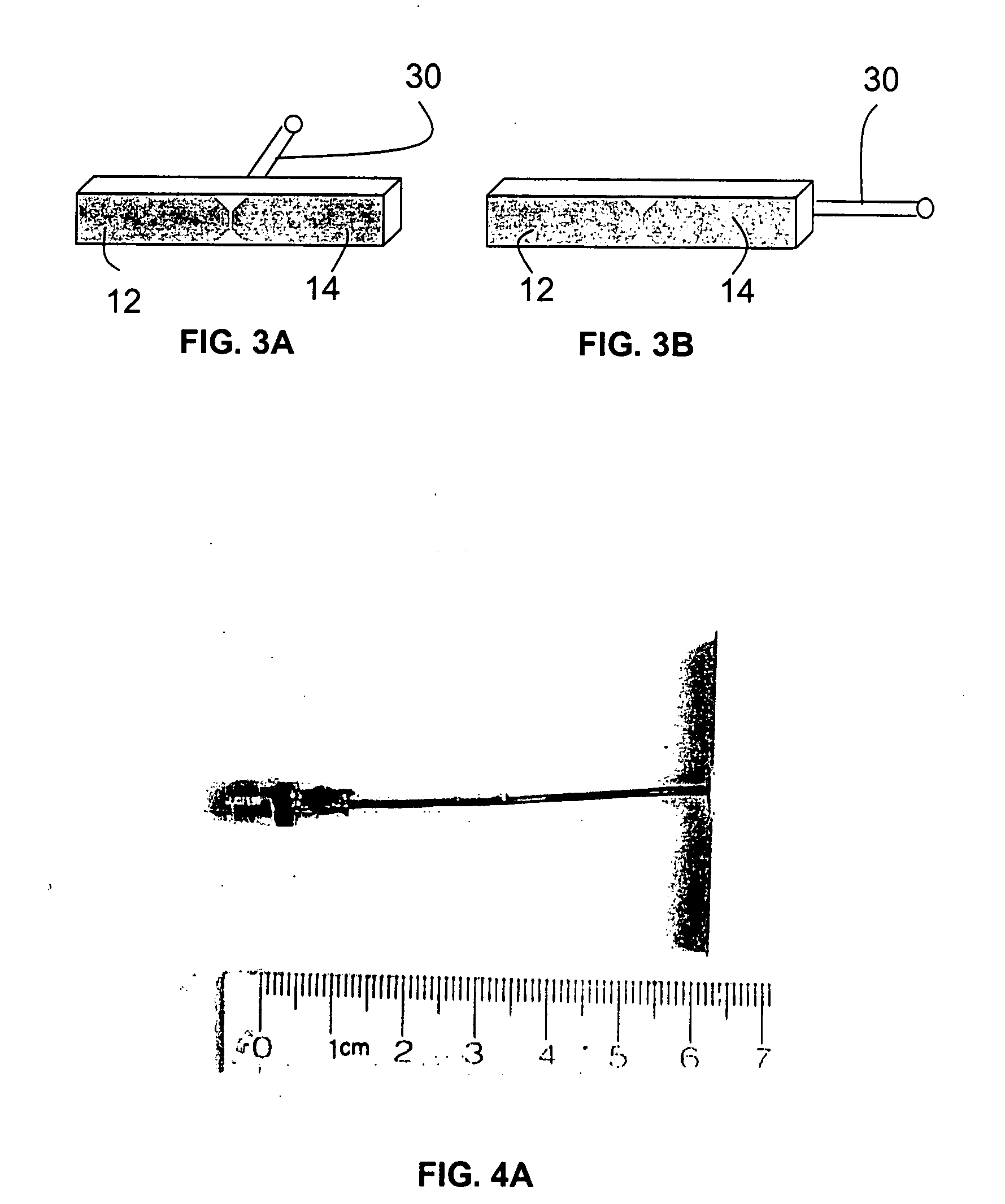
[0029] A preferred antenna package is a PCB antenna package on or within a plastic substrate, for example an epoxy and glass fiber substrate, e.g., an FR4 substrate that may be very thin, for example less than 1 mm. Generally, antennas of the invention have small footprints, e.g. lengths of less than 100 mm, and preferably less than 50 mm, and widths of less than 40 mm and preferably less than 15 mm. Thicknesses may be very thin, for example preferably less than 0.5 mm and generally less than one millimeter or a few millimeters. Preferred embodiments include particular dimensions and materials, which will be described below, but the invention is not so limited in its broader aspects. For example, embodiments of the invention include substrates with selected and optimized electrical properties and thicknesses for different bands and performance, and, similarly, different conductors can be used without modifying the design methodology that will be presented below.

[0030] An example sy...


PUM


Abstract

A small footprint dipole antenna of the invention for WLAN applications is designed for full natural resonance in a single band, e.g., the 2.4 GHz band, and uses a matching network to for artificial resonance at a second band, e.g., the 5 GHz band. The natural impedance of the dipole in second band is set in a range that produces an efficient antenna with substantial range in both of the first and second bands.

Description

CROSS REFERENCE TO RELATED APPLICATIONS [0001] This application claims priority under 35 U.S.C. 119, to provisional application No. 60 / 542,061, filed on Feb. 5, 2004.FIELD OF THE INVENTION [0002] A field of the invention is antennas. Another field of the invention is wireless networks, including, for example, local area networks that operate wirelessly. Another field of the invention is routers, such as those used to route wireless communications in a wireless network. Another field of the invention is inventory control and management systems, and in particular, systems that use a handheld reader, such as a bar code reader, that communicates wirelessly with a local or wide area network, for inventory control and management. Antennas of the invention have a small footprint, having lengths less than, for example 50 mm, widths of less than, for example 15 mm and thicknesses of less than, for example, one millimeter. BACKGROUND [0003] Wireless local area networks (WLAN) are an important...

Claims


Application Information

Patent Timeline
Patent Type & Authority Applications(United States)
IPC IPC(8): H01Q5/00H01Q5/335H01Q9/28
CPCH01Q9/28H01Q5/335H01Q9/285
Inventor ZHANG, ZHIJUNLANGER, JEAN CHRISTOPHE
Owner AMPHENOL T & M ANTENNAS
Why Eureka
Try Eureka