Synchronizing of time display and integration cameras

a technology of time display and integration camera, which is applied in the direction of color television details, television system details, television systems, etc., can solve problems such as distortion in the output image of tdi line scan cameras

Inactive Publication Date: 2005-10-27
UNIV TECH INT
View PDF5 Cites 9 Cited by
  • Summary
  • Abstract
  • Description
  • Claims
  • Application Information

AI Technical Summary

Benefits of technology

[0011] The difference between the charge movement and the image movement speed causes distortion in the output image of a TDI line scan camera. This distortion is due to the low-pass filtering effect of the TDI process when it is not ynchronized. The algorithms of the present invention generally synchronize the charge movement spe...

Problems solved by technology

The difference between the charge movement and the image movement speed causes distortion in the output image of a T...

Method used


Image

  • Synchronizing of time display and integration cameras
  • Synchronizing of time display and integration cameras
  • Synchronizing of time display and integration cameras

Examples


examples

[0059] The following examples are intended only to exemplify embodiments of the present invention, not to limit the invention claimed herein.

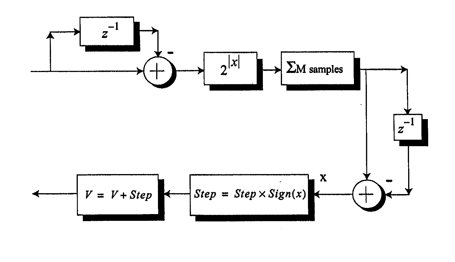
[0060] The algorithms of the present invention were tested using a Matlab™ simulator. Results from this simulation for the architecture shown in FIG. 7 is given in FIG. 10. Although the original design specifications of the control system did not require it to match sudden changes in the image speed, the simulation results show that the algorithm can match almost a 20% step change in the image speed. FIG. 11 shows the response of the system with the 3-tap filter and absolute value function from FIG. 8.

[0061] It was found that the system shown in FIG. 8 does not converge as fast as the one shown in FIG. 7 and it is also less stable. However, the system shown in FIG. 8 does have the advantage of lower processing complexity. FIG. 12 shows the response of the system with an adaptive step size from FIG. 9A. As may be seen, this system matches the ...


PUM


Abstract

A method and system for synchronizing time delay and integration cameras by measuring high frequency components of the TDI camera output and varying either charge velocity within the camera or image velocity, in order to maintain the maximum point of the high frequency components.

Description

FIELD OF INVENTION [0001] The present invention relates to a method and apparatus for synchronizing time delay and integration cameras. BACKGROUND OF THE INVENTION [0002] Image sensors convert light intensity to voltage or current and are widely implemented in video cameras and digital cameras. The development of solid state image sensors has made modern machine vision a viable process for the monitoring and control of industrial processes. Industrial line-scan cameras are usually either complementary metal-oxide semiconductor (CMOS) or charge-coupled device (CCD) designs. Both CMOS and CCD imagers are constructed from silicon, which gives them fundamentally similar properties of sensitivity over the visible and near infrared spectrum. Both types of imagers convert light into electric charge and process it into electronic signals. In a CCD sensor, the electrons are stored in potential wells that are formed under sets of electrodes. The stored charge in each well may be serially tran...

Claims


Application Information

Patent Timeline
IPC IPC(8): H04N5/225H04N5/3745H04N5/335H04N5/357
CPCH04N5/37206H04N3/1525H04N25/711H04N25/768
Inventor BAYKAL, IBRAHIM CEMJULLIEN, GRAHAM A.
Owner UNIV TECH INT
Why Eureka
Try Eureka