Method and apparatus for in situ inspection of reformer tubes

a technology of reformer tubes and in situ inspection, which is applied in the field of in situ inspection of reformer tubes, can solve the problems of corrosive substances, tube failure, and significant replacement cost of tubes, and achieve the effects of preventing tube failure, huge potential, and optimizing production

Inactive Publication Date: 2005-10-27
QUEST TRUTEC
View PDF3 Cites 21 Cited by
  • Summary
  • Abstract
  • Description
  • Claims
  • Application Information

AI Technical Summary

Benefits of technology

[0021] The use of the internal laser mapping technique is not only useful in preventing tube failure b

Problems solved by technology

These tubes represent a significant cost for replacement and can be a major source of plant unavailability if unplanned failures occur.
Such tubes are frequently subjected to pressure changes and contact with corrosive substances.
Under such situations creep, metal dusting, and surface irregularities frequently develop.
If left untreated, creep will develop into cracks that will propagate leading to failure of the tube.
The plant operator is faced with balancing production needs against tube life and risk of tube failure.
One of the major concerns in plant operation is that the reformer tubes operate at an elevated temperature such that they are susceptible to a failure mechanism referred to as “creep”.
However, with the trend towards larger tube diameters and longer intervals between turnarounds, the detection of such defects may not allow for sufficient time for forward planning of tube replacements.
Also, such “end of life” techniques do not allow any differentiation between the “good” tubes.
Typically, destructive testing

Method used


Image

  • Method and apparatus for in situ inspection of reformer tubes
  • Method and apparatus for in situ inspection of reformer tubes
  • Method and apparatus for in situ inspection of reformer tubes

Examples


Embodiment Construction

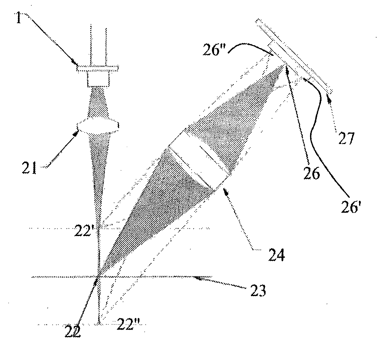
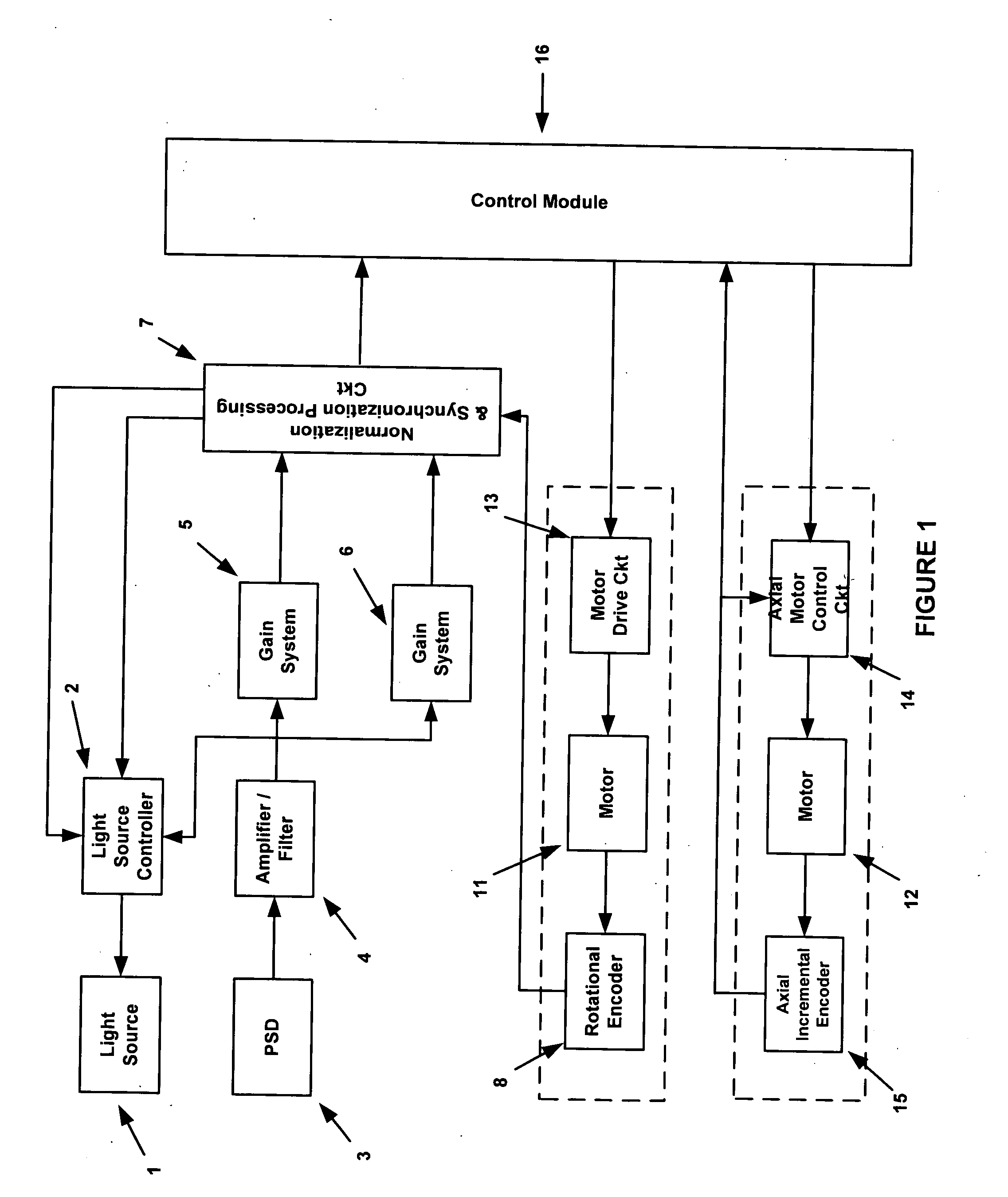
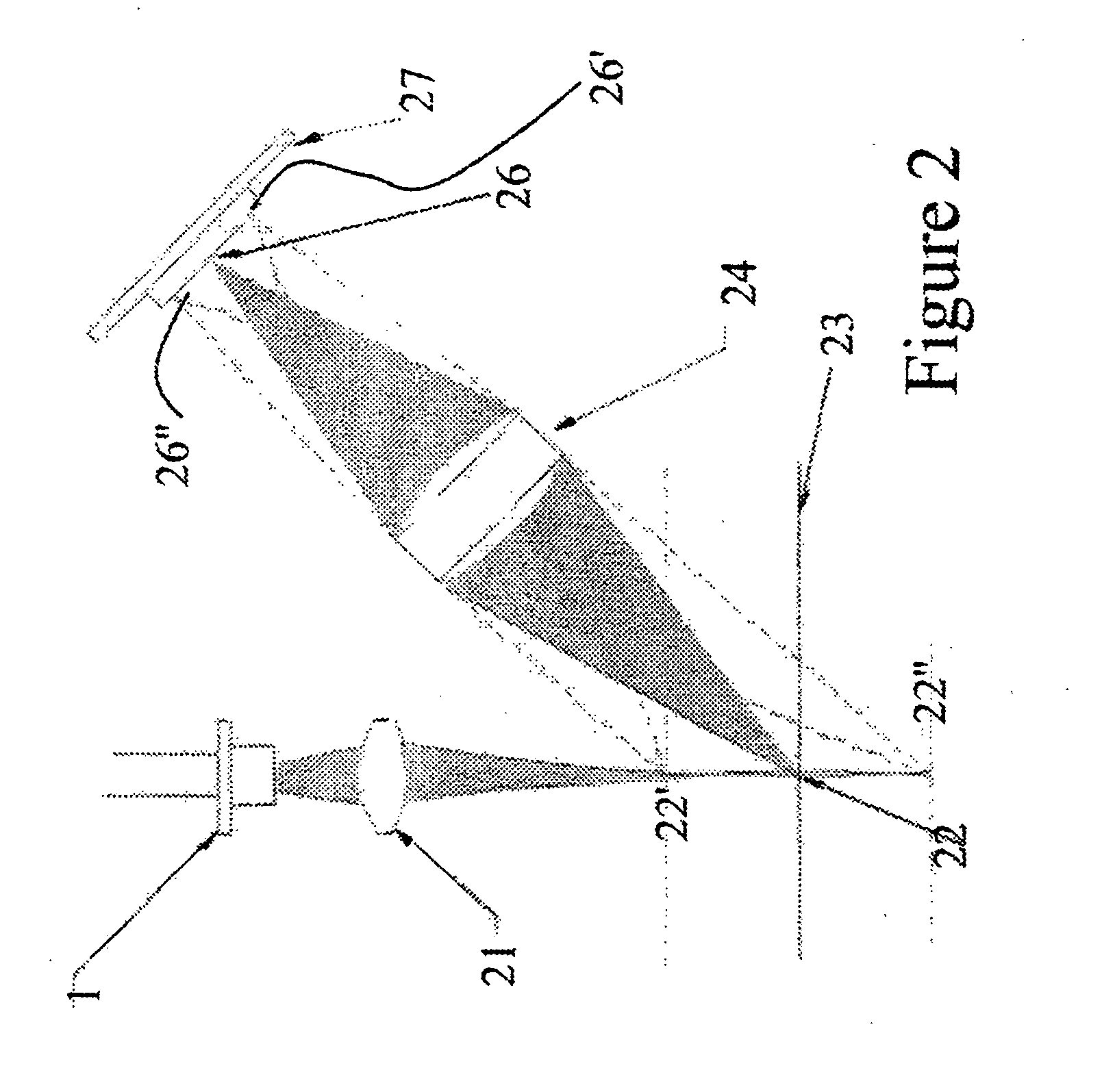
[0030]FIG. 1 is a block diagram of an embodiment of the invention. Components may be either hardware components or software modules as described below. The probe includes a light source 1. The purpose of the light source 1 is to project a spot of light on the surface (not shown) to be inspected. Light source 1 is typically a laser diode or light emitting diode (LED). A light source controller 2 is connected to light source 1. Controller 2 sets and controls the optical power level of light source 1. The power level may either be fixed or varied to produce a preset signal level.

[0031] A position sensitive photo detector (PSD) 3 is situated so as to detect the spot made by light source 1. Photo detector 3 may be a lateral effect photodiode, photodiode array, or charge coupled device (CCD). This description assumes the device chosen for 3 is a lateral effect photodiode. Detector 3 may have either one or two axes, dependant upon the specific measurement geometry. In this description onl...


PUM


Abstract

A method and apparatus for accurately determining the interior profile of cylindrical objects such as reformer catalyst tubes is described. The radius of the tube is measured from the axis of the tube for each point of the interior surface by calculating the angle of a reflected light beam and the deviation thereof. A first embodiment reflects an light beam off of the interior surface of the cylinder and measures the angle of the light reflected from the interior of the cylinder. A second embodiment removes rotating parts by using a cone mirror to reflect a ring of light onto the interior of the cylinder. Signal processing means are provided to reduce surplus signals allowing transmission of only useful information.

Description

CLAIM FOR PRIORITY [0001] This application claims priority under 35 § U.S.C. § 120 to application Ser. No. 09 / 713,415, filed Nov. 11, 2000, entitled “Method And Apparatus For In Situ Inspection of Reformer Tubes,” which is hereby fully incorporated by reference. CROSS REFERENCE TO RELATED APPLICATIONS [0002] The present patent application is related to our co-pending application entitled “A Method For Processing In Situ Inspection Reformer Tube Data,” U.S. application Ser. No. 10 / 707,629 filed Dec. 25, 2003, which is incorporated by reference as if fully set forth herein and “A Method for Reformer Tube In Situ Inspection Radius Calculation”, U.S. application Ser. No. 10 / 707,630 filed Dec. 25, 2003, which is incorporated by reference as if fully set forth herein.BACKGROUND OF THE INVENTION [0003] 1. Field of the Invention [0004] The present invention relates to inspection of materials, and more particularly to the inspection of the surface of materials for creep, metal dusting, irreg...

Claims


Application Information

Patent Timeline
IPC IPC(8): G01N21/954G06T7/00
CPCG01N21/954G06T2207/30164G06T7/0004
Inventor BONDURANT, PHILLIP D.LILLEY, RONALD C.ROBERTS, RICHARD D.COWLING, THOMAS J.
Owner QUEST TRUTEC
Why Eureka
Try Eureka