Block copolymer and nanofiller composites

a composite material and copolymer technology, applied in the field of polymer nanocomposites, can solve the problems of cost and customer special requirements, and the traditional method is difficult to meet the needs of customers

Active Publication Date: 2005-10-27
RENESSELAER POLYTECHNIC INST
View PDF11 Cites 15 Cited by
  • Summary
  • Abstract
  • Description
  • Claims
  • Application Information

AI Technical Summary

Benefits of technology

[0004] As mentioned above, block copolymers are polymers whose molecular chains consist of incompatible segments that can self-assemble to form separated phases or microdomains. They have wide industrial applications as biomedical materials, engineering thermoplastics and elastomers, and optical and electrical materials. The versatile properties and applications of block copolymers are determined by their phase-separated microdomains. Traditionally, the microdomains of block copolymer systems were controlled by changing the ratio of the blocks of the copolymer. This can strongly influence their phase separation, and thus their overall properties. From the viewpoint of practical applications, this traditional method has difficulties related to cost and customers' special requirements. Thus, a new method to modify the properties of block copolymers is desired. The inventors have discovered that combining copolymers with nanoscale fillers (metal; ceramic; organic nanoparticles such as nanotubes and nanofibers; materials that are modified such as organoclays; or a combination of these) can be the solution. By carefully modifying the surfaces of the nanoscale fillers, the inventors have found they can either chemically tether the block copolymers onto the nanofillers or through other means (such as hydrogen bonds or van der Waals forces) control the interactions between the copolymers and the nanofillers. The interactions can control the self-assembly of the phase-separated microdomains of the block copolymers and, thus, control the overall properties of the block copolymers.

Problems solved by technology

From the viewpoint of practical applications, this traditional method has difficulties related to cost and customers' special requirements.

Method used


Image

  • Block copolymer and nanofiller composites
  • Block copolymer and nanofiller composites
  • Block copolymer and nanofiller composites

Examples


example 1

Sample Preparation

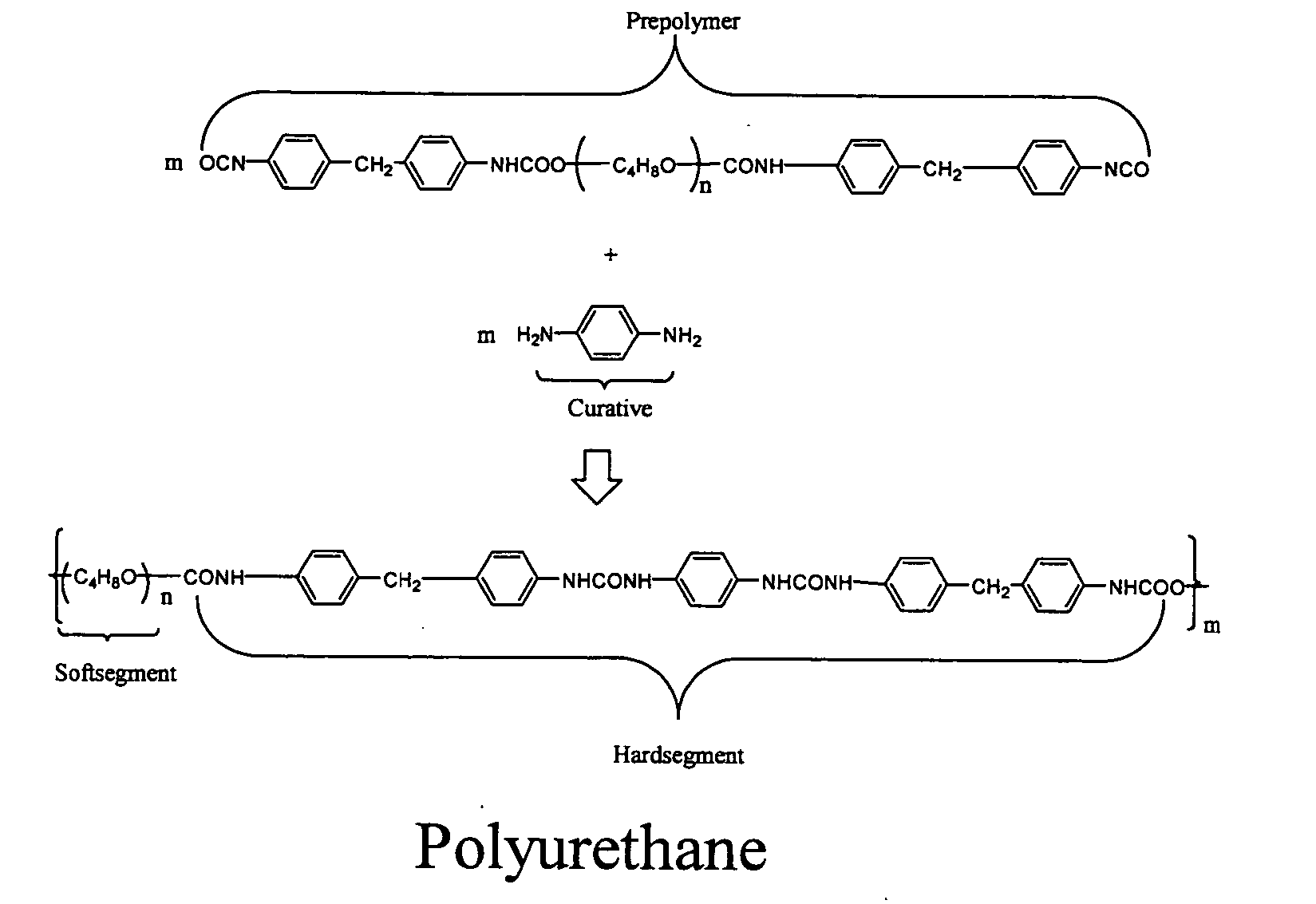
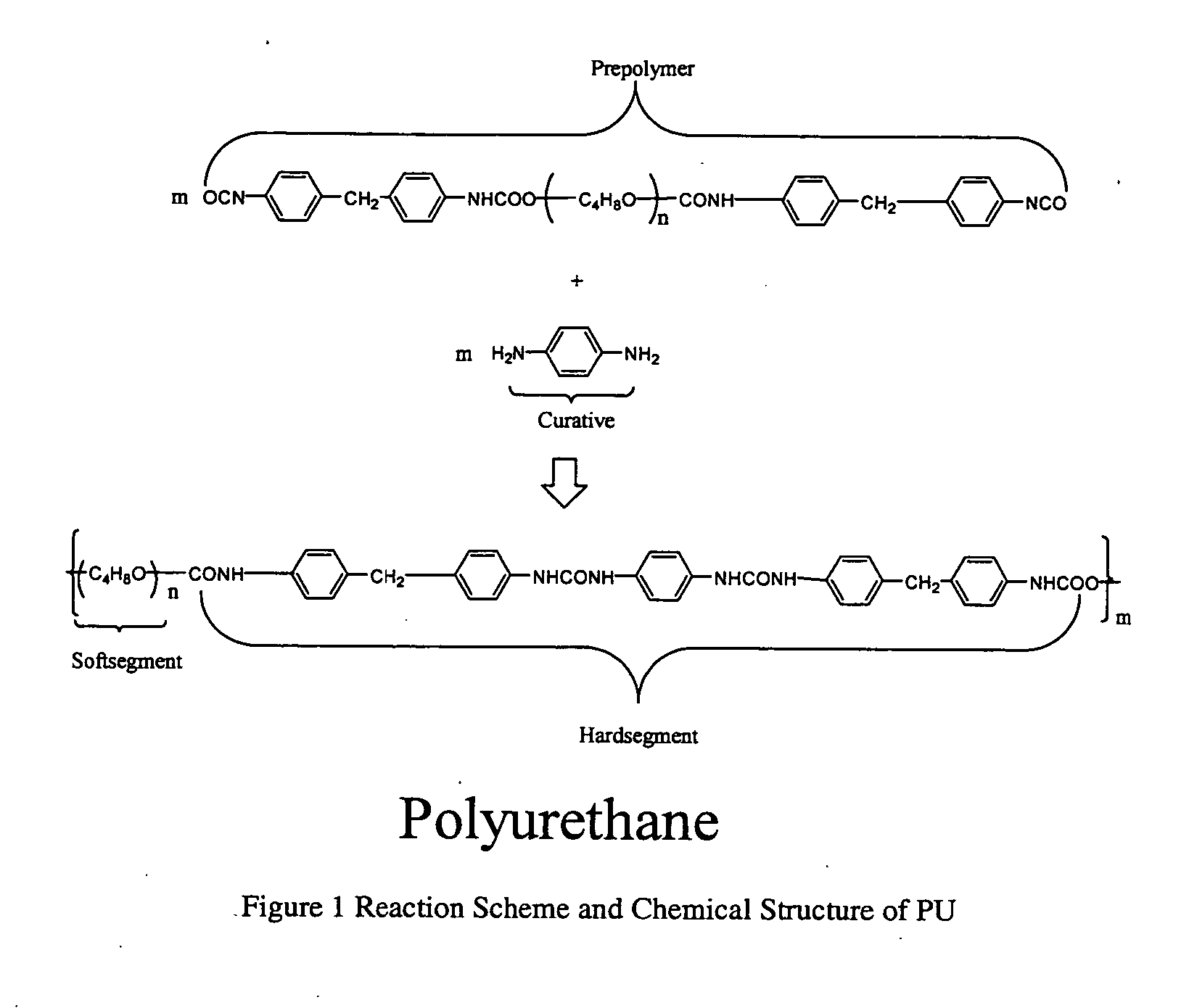
[0061] Typical procedure for composites: Equal molar ratio of a degassed PU prepolymer (TDI-PPG Prepolymer; wt % NCO is 6.32; Airthane® PPT-95A Prepolymer; Air Products) and a diamine curative (aromatic diamine; Lonzacures MCDEA Curative; Air Products) were dissolved in purified THF to form 15% solution at 25° C. ZnO particles (used as received; nano-size=33 nm; Nanophase Technologies Corporation; micron-size=˜2.5 μm; Atlantic Equipment Engineers) were dispersed in THF to form a 10% solution with a sonicator-solutions that contain 10-20% ZnO may also be used. The two solutions were combined together and sonicated for 20 min in ice / water bath. Subsequently the mixture was concentrated to 60% solution. The solution was cast into moulds and cured at 40° C. for 8 h, and then cured at 110° C. for 24 h to form thin films with different thickness from 0.2 to 1 mm. The preparation of neat PU uses a similar procedures.

[0062] In general, the common preparation procedure of...

example 2

DMTA and Tensile Tests

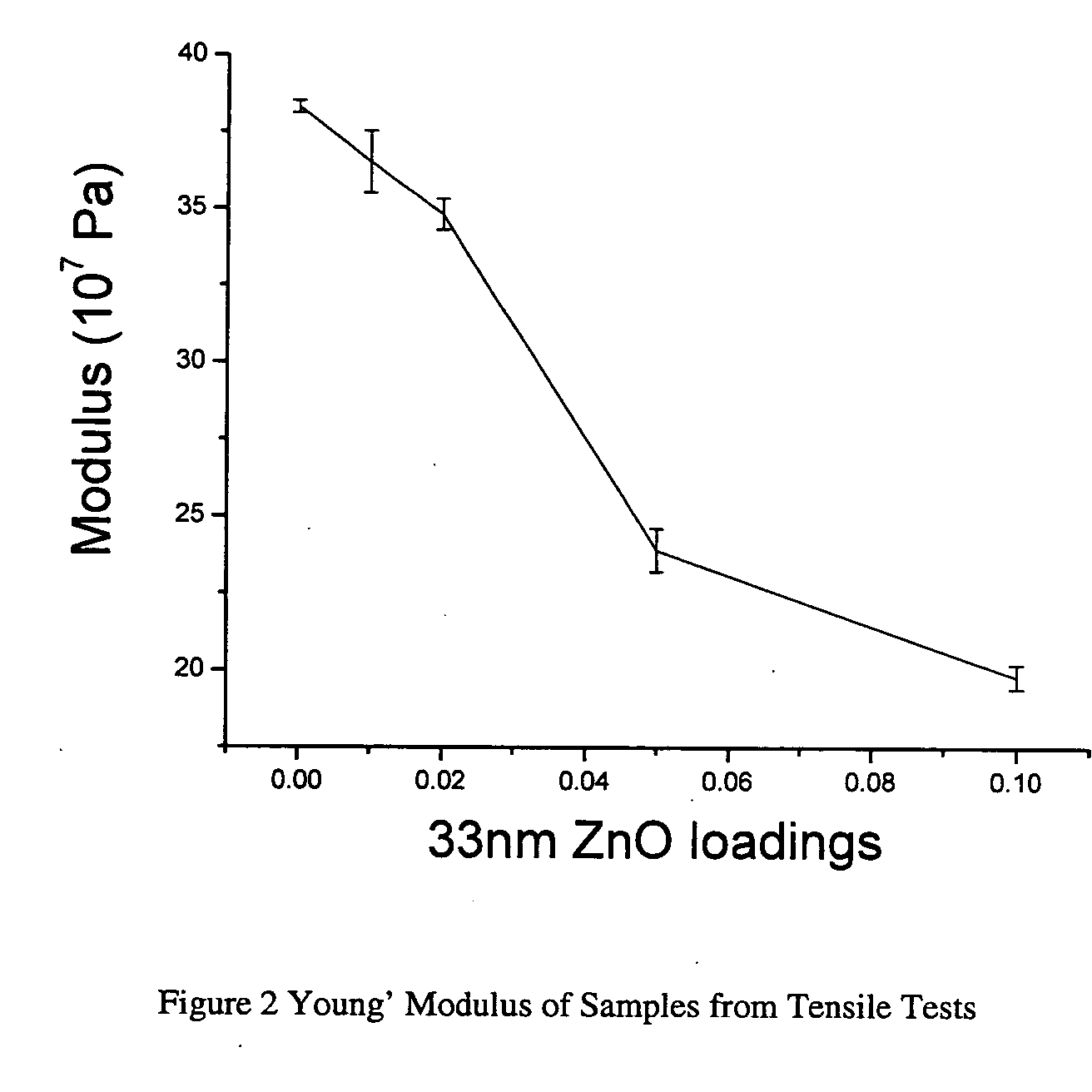
[0064] The mechanical responses of samples were measured with a DMTA (DMTA V, Rheometric Scientific) and Instron 8562. Two kinds of DMTA measurements were performed: 1, Dynamic (1 Hz, 6.2832 Rad / s) strain sweep at room temperature (21° C.); 2, Dynamic (1 Hz, 6.2832 Rad / s) temperature ramp sweep at 0.1% strain and 2° C. / min rate from −130° C. to 200° C. Tensile tests were performed to give the Young's Modulus and elongation of samples. Each data point is averaged from 3-6 samples.

[0065]FIG. 2 is the Young's Modulus of the neat PU and its composites with different ZnO nanoparticles loadings from tensile tests. FIG. 3 is the storage modulus vs. strain for samples from DMTA tests. All these tests were performed at around 21° C. All detailed DMTA and tensile tests data are listed in Table 1.

TABLE 1Data from Tensile Tests and DMTA TestsStorageYoung'TgModulusModulusElongationMaterial(0° C.)(107 Pa; 0.1%)(107 Pa)(%)PU2.919.638.3 ± 0.2492 ± 98 1 wt % 33 nm ZnO017.63...

example 3

AFM Measurements

[0070] The AFM (Autoprobe CP; Park Scientific Instruments; with tip, ultralevel D; spring constant ˜18N / m; and MultiMode Scanning Probe Microscope; Digital Instruments) measurements were conducted at room temperature using the tapping mode with different forces. The samples were neat PU and the composite with 5 wt % 33 nm ZnO in films of (1) 500 μm thickness and (2) less than 1 μm (10 wt % THF solutions were spin coated at 3000 rpm) on silicon wafers.

[0071] AFM was used to determine the microstructures of PU and composites. Until now real space characterization of the phase-separated morphology in PU is still a challenging task. Transmission electron microscopy (TEM) studies on stained films have yielded some insight, but the experiments are limited by the efficacy of the staining, the kind of the PU and the possibility of the electron beam damage. In recent years, atomic force microscopy (AFM) has been used to image the microdomains in the PUs. In PUs, the mechani...


PUM

PropertyMeasurementUnit
Tgaaaaaaaaaa
Tgaaaaaaaaaa
image sizeaaaaaaaaaa

Abstract

PU / ZnO nanocomposites are provided wherein the addition of less than 1 vol % 33 nm ZnO nanoparticles into a PU matrix effect a decrease in the Young's Modulus and storage modulus of the polymer, while simultaneously effecting an increase glass transition temperature of the polymer. Detailed experiments are described (e.g., FTIR, DMTA, FESEM and AFM) that suggest that the reaction between hydroxyl groups of the ZnO nanoparticles and isocyanate groups of the polyurethane prepolymer disrupts the self-assembly of the phase separation in PU. Phase separation is responsible for the good mechanical properties of PU. Further, detailed experiments suggest that the increase of the glass transition temperature results from the crosslinking effect of the ZnO nanoparticles.

Description

[0001] The present application claims the benefit of U.S. provisional application Ser. No. 60 / 553,133 filed on Mar. 16, 2004, which is incorporated herein by reference in its entirety. The present invention relates generally to polymer / nanofiller nanocomposites and more particularly to controlling the polymer microstructure by selecting certain nanofillers.BACKGROUND OF THE INVENTION [0002] In recent years, polymer nanocomposites, which are composed of polymer matrices and nano-size fillers, attracted extensive research interests around the world. It has been found that these new kinds of materials have many advantages over the traditional ones such as increased strength without weakening other mechanical properties, decreased gas permeability, improved heat resistance, and enhanced electrical conductivity. Special interest has been focused on block copolymer / nanofiller systems, because in the general polymers / nanofillers system, until now, it is almost impossible to array nanofille...

Claims


Application Information

Patent Timeline
Patent Type & Authority Applications(United States)
IPC IPC(8): A61K9/50C08K3/22
CPCB82Y30/00C08K2201/011C08K2003/2296C08K3/22Y10T428/12569
Inventor ZHENG, JUNRONGOZISIK, RAHMISIEGEL, RICHARD W.
Owner RENESSELAER POLYTECHNIC INST
Why Eureka
Try Eureka