End face structure of optical fiber, optical fiber laser, and laser processing apparatus

a laser processing and end face technology, applied in the direction of cladded optical fibre, instruments, active medium materials, etc., can solve the problems of critical damage, increase production cost, and decrease in population inversion

Active Publication Date: 2005-11-03
THE FUJIKURA CABLE WORKS LTD
View PDF7 Cites 23 Cited by
  • Summary
  • Abstract
  • Description
  • Claims
  • Application Information

AI Technical Summary

Benefits of technology

[0017] The present invention was conceived in view of the above-mentioned background, and an object thereof is to provide a low-cost end face structure and optical fiber connection that prevents damage to end faces of optical fibers that output high power laser light, an optical fiber laser having such an end face structure, and a laser processing apparatus including such an optical fiber laser.

Problems solved by technology

With such a high power density, burn-in caused by adhered dust or contaminants may destroy the end face of the optical fiber, which may result in critical damage.
In some cases, laser oscillation may occur, which results in a decrease in the population inversion.
Accordingly, expensive filler are used since there are not many options for filler materials, which results in increased production cost.
In addition, when an ultraviolet curing resin is used, if the length L of the optical filler 17 shown in FIG. 2 is long, the curing resin is not completely cured since ultraviolet light does not reach the region far from the surface and air bubbles are present.
It is difficult to form an optically complete continuous junction.
Furthermore, the resin exhibits poor resistance to optical power, and the resin may be burned
Furthermore, providing a dielectric multilayer film in the anti-reflection treatment requires vacuum processing, which is time-consuming and expensive.

Method used


Image

  • End face structure of optical fiber, optical fiber laser, and laser processing apparatus
  • End face structure of optical fiber, optical fiber laser, and laser processing apparatus
  • End face structure of optical fiber, optical fiber laser, and laser processing apparatus

Examples


examples

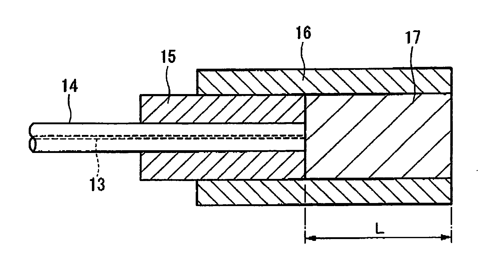
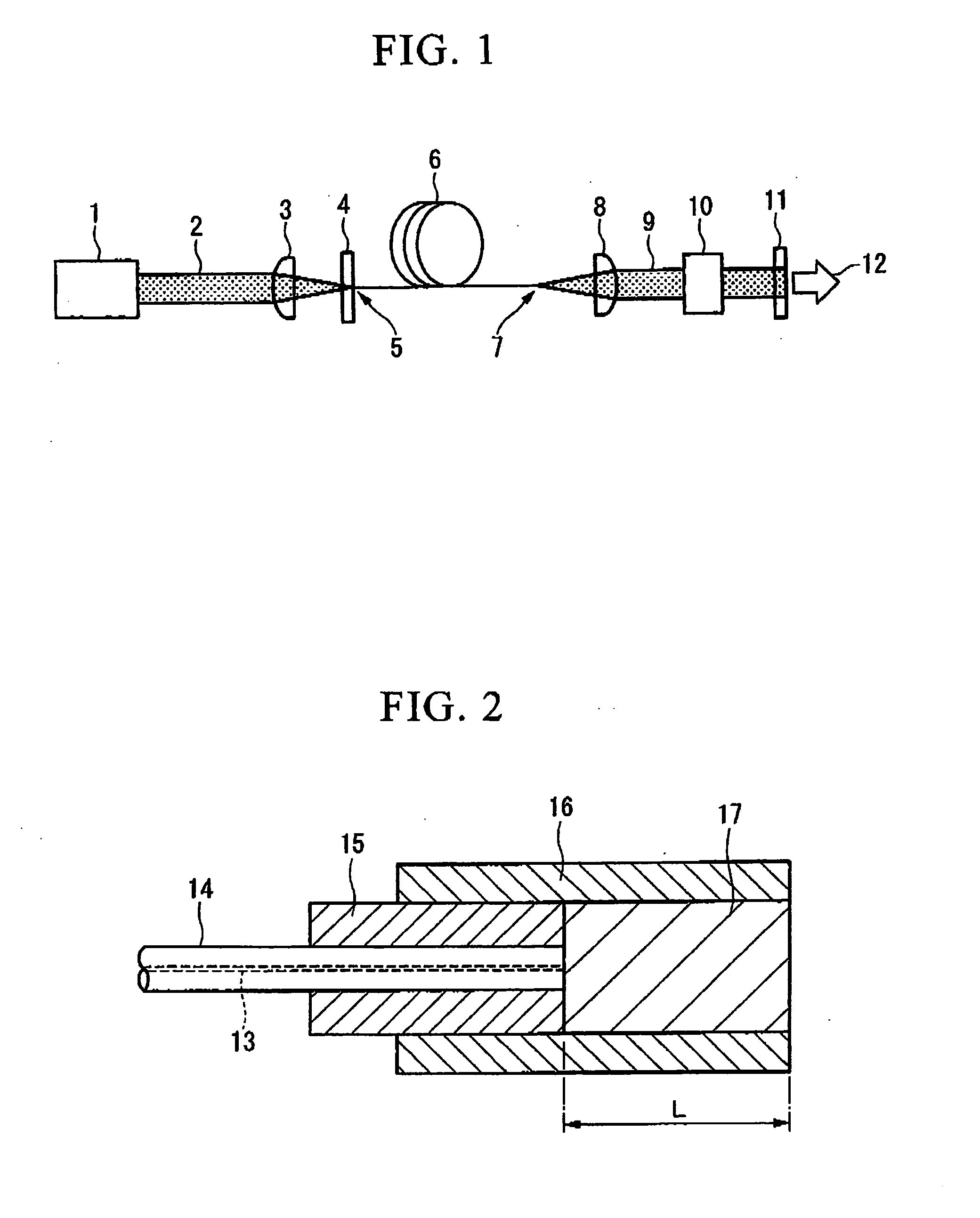
[0057] The end face structure of the present invention was fabricated. An erbium-doped optical fiber was used as the rare-earth doped optical fiber. The erbium-doped optical fiber has a double cladding structure having first and second claddings, in which the diameter of the core was 40 μm, the diameter of the first cladding was 400 μm and the diameter of the second cladding was 530 μm. Furthermore, the second cladding was a polymer cladding, and the second cladding at the fuses-spliced portion was stripped by soaking it in an organic solvent. A coreless fiber having a diameter of 280 μm was used. The refractive index of the core of the erbium-doped optical fiber and the coreless fiber was 1.53.

[0058] Furthermore, an ultraviolet curing resin having a refractive index of 1.56 was used as the coating material. Although an ultraviolet curing resin was used in this example, the coating material is not limited to ultraviolet curing resins, and other resins, such as thermal curing resins...


PUM

PropertyMeasurementUnit
refractive indexaaaaaaaaaa
lengthaaaaaaaaaa
lengthaaaaaaaaaa

Abstract

An end face structure of an optical fiber includes a coreless fiber fused to an emitting end face of the fiber optical fiber and a coating material disposed around at least the coreless fiber, a refractive index of the coating material being higher than a refractive index of the coreless fiber.

Description

BACKGROUND OF THE INVENTION [0001] 1. Field of the Invention [0002] The present invention relates to an end face structure of an optical fiber that emits laser light, to an optical fiber laser including such an end face structure, and to a laser processing apparatus including such an optical fiber laser. [0003] Priority is claimed from Japanese Patent Application No. 2004-120006, filed Apr. 15, 2004, which is incorporated herein by reference. [0004] 2. Description of Related Art [0005] In recent years, lasers have been employed in various fields, including material processing apparatuses, medical treatment appliances, and measuring instruments. Especially in the field of material processing apparatus, laser light has been widely used because high-precision machining is made possible with laser light having a very small beam spot and a high power density since laser light exhibits excellent focusing property, because non-contact processing with little damage to a workpiece is possibl...

Claims


Application Information

Patent Timeline
Patent Type & Authority Applications(United States)
IPC IPC(8): G02B6/02G02B6/00G02B6/26G02B6/42H01S3/00H01S3/06H01S3/067H01S3/0941
CPCG02B6/262H01S3/005H01S3/06708H01S3/117H01S3/06745H01S3/094007H01S3/0941H01S3/06729
Inventor KITABAYASHI, TOMOHARUSAKAI, TETSUYA
Owner THE FUJIKURA CABLE WORKS LTD
Why Eureka
Try Eureka