Oil pump that can be driven by means of an electric motor

a technology of oil pump and electric motor, which is applied in the direction of piston pump, positive displacement liquid engine, liquid fuel engine, etc., can solve the problem that the electric motor cannot be embodied as the high-inertia electric motor of the electric locomotive drive, and achieve the effect of preventing the flow of fluid away, facilitating maneuverability, and facilitating the flow of fluid

Inactive Publication Date: 2005-11-03
DAIMLER AG
View PDF4 Cites 14 Cited by
  • Summary
  • Abstract
  • Description
  • Claims
  • Application Information

AI Technical Summary

Benefits of technology

[0009] One advantage of the invention is that a separate cooling system is provided for the oil pump, with the oil pump itself supplying oil to the actual electric motor which drives it. Entrapped oil which emerges from the oil pump is diverted to its electric motor for cooling purposes.
[0010] As a result of the self-cooling, the risk of failures which are associated with thermal overloading of the electric motor are reliably ruled out. In particular, the insulation layers of the windings are reliably cooled.
[0011] The oil pump is preferably arranged within the gearbox housing in the gearbox oil / air space of the gearbox so that a favorable “packaging” is obtained, i.e. the hybrid drive with an oil pump can be accommodated, with only a slightly enlarged overall installation space in the same installation space in which otherwise identical drive trains with a purely internal combustion engine drive are accommodated. As a result, the same bodywork structure can be used for hybrid vehicles and standard vehicles.
[0012] In particular, when a hydrodynamic torque converter—as a starting element of the gearbox—is replaced with an electric motor for the hybrid drive, the electrically operated oil pump can even be installed with corresponding overall installation space conditions of the locomotive drive electric motors even without enlarging the overall space in comparison with the standard drive.
[0013] When the oil pump according to the invention is arranged inside the gearbox housing in the gearbox oil / air space of the gearbox, there is a larger room for maneuver in the design of the gearbox housing, since the latter does not need to conduct away the heat of the electric motor of the oil pump since the heat can be transported to any desired location via the gearbox oil for the purposes of cooling. As a result, approximately 200 Watt thermal power can be carried away from a high-torque vehicle. In this case, the oil balance of the gearbox is not affected by the additional volume flow rate required for the additional cooling of the electric motor of the oil pump. In this arrangement in the gearbox oil / air space, the electric motor of the oil pump is advantageously configured so as to be insensitive to the gearbox oil.
[0014] As shown in the drawing, the oil pump distributes the oil uniformly to the stator which is fixed to the housing. At the same time, the oil is diverted in a particularly advantageous way into an annular gap by utilizing gravity and a centrifugal effect, which gap is formed between the rotor of the electric motor and a gearbox housing wall. Roller bearings of the rotor are also cooled / lubricated in a particularly advantageous way by the oil in the annular gap. The oil is prevented from flowing away freely by a retaining edge. The oil which is partially accumulated is forced from the annular gap into a rotor bore. This rotor bore can end in particular between two magnets underneath the banding of the rotor. This banding may particularly advantageously be a tubular component, which in addition to the function of conducting oil, has the function of absorbing the centrifugal forces of the magnets. If the oil stream through the rotor bore impinges on the banding, the oil stream can be particularly advantageously diverted to two axial annular outlets of the rotor.

Problems solved by technology

As a result, the electric motor cannot itself be embodied as a high-inertia electric motor of the electric locomotive drive.

Method used


Image

  • Oil pump that can be driven by means of an electric motor
  • Oil pump that can be driven by means of an electric motor

Examples


Embodiment Construction

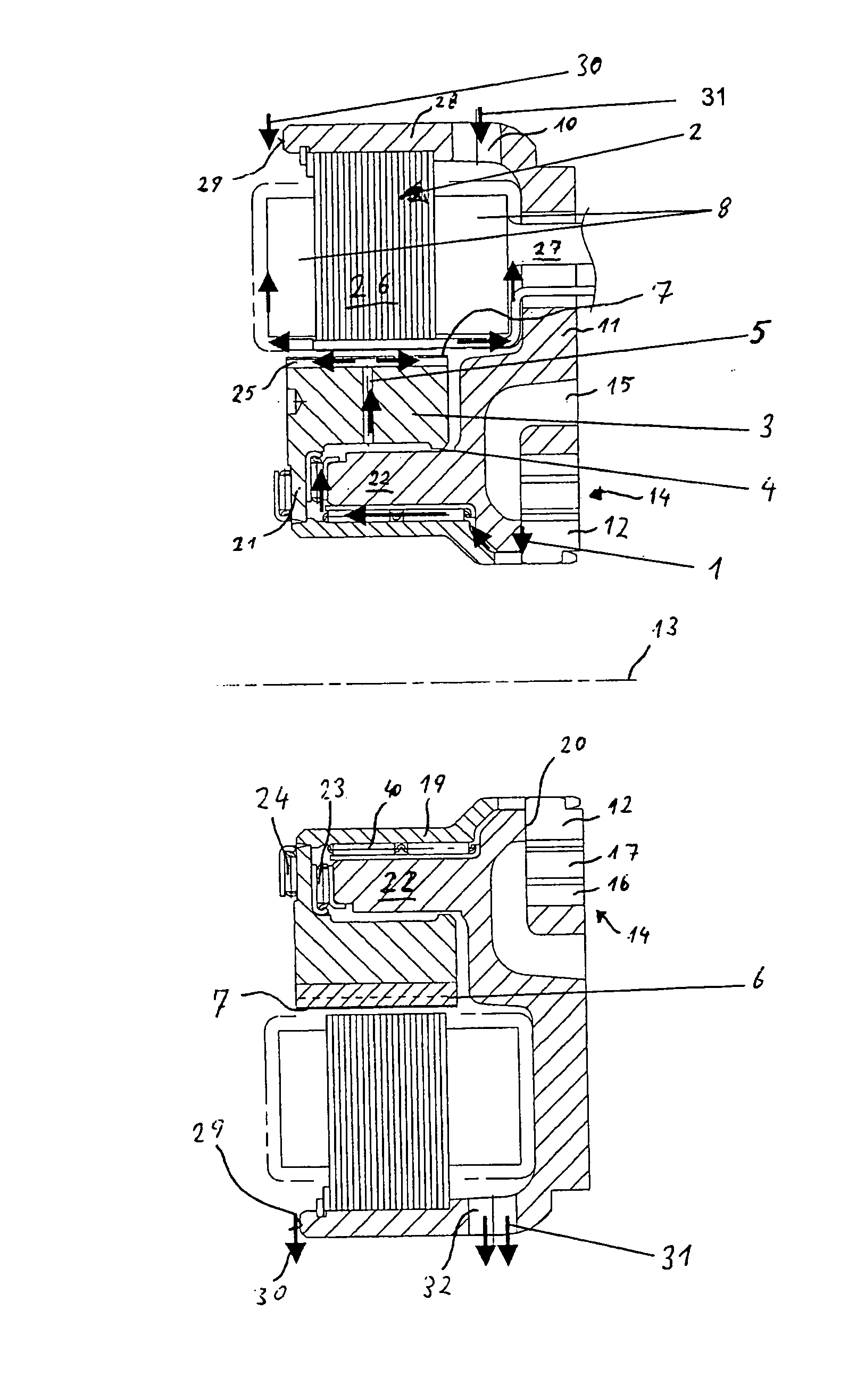
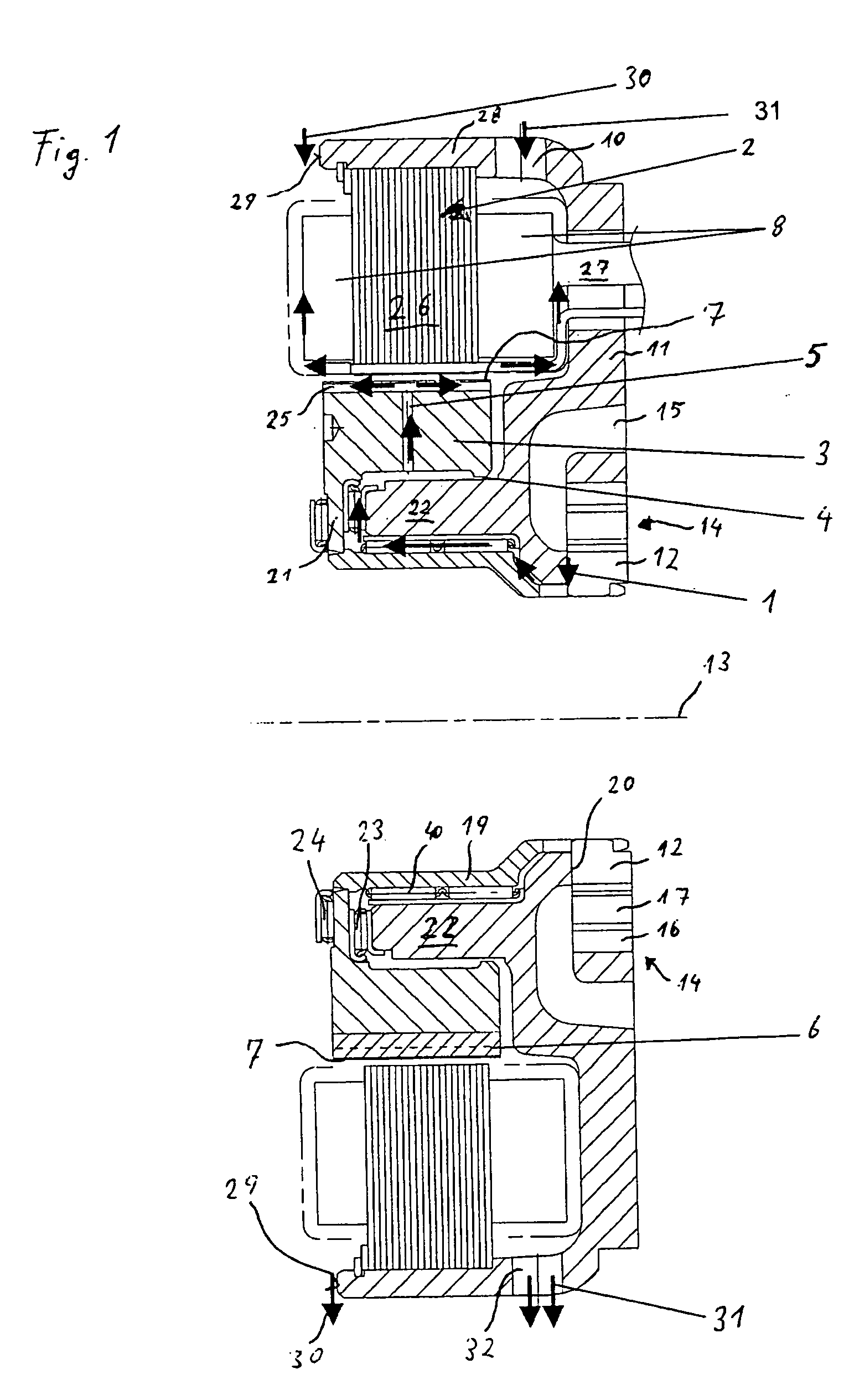
[0028] In the drawing, FIG. 1 shows a detail from a drive train of a hybrid vehicle. Such a drive train comprises an electric machine which is arranged between an internal combustion engine (not illustrated in more detail) and a gearbox of a motor vehicle. The motor vehicle may be driven either by the internal combustion engine or alternatively by the electric machine. The motor vehicle can also be operated in a “boost operating mode”, either with the internal combustion engine or the electric machine, in order to increase the driving-off / acceleration power. Such a drive train is described in PCT / EP03 / 11979, whose content is hereby incorporated by reference.

[0029] The internal combustion engine and the gearbox are arranged coaxially with respect to a central axis 13. This central axis 13 is used below as a reference axis for the expression “axial”. A pressure-regulated oil pump is located inside a gearbox housing of the gearbox. This oil pump is embodied as a crescent pump 14. A wo...


PUM


Abstract

An electrically operated crescent pump of a hybrid drive train conducts entrapped oil emerging from the oil pump to windings of the stator in order to cool the electric motor of the pump.

Description

BACKGROUND OF THE INVENTION [0001] 1. Field of the Invention [0002] The invention relates to an oil pump which can be driven by an electric motor and supplies working pressure to a gearbox. [0003] 2. The Prior Art [0004] German Patent No. 101 60 466 C1 describes an oil pump which can be driven by an electric motor. This oil pump is applied in a drive train of a hybrid vehicle. [0005] In addition, PCT / EP03 / 11979 (not published before the priority date of this application) describes a drive train of a hybrid vehicle. This drive train also has an oil pump for the gearbox. SUMMARY OF THE INVENTION [0006] It is therefore an object of the invention to provide a particularly operationally reliable pump which can be driven electrically. [0007] This object is achieved according to the invention by an oil pump for supplying a gearbox having a housing with working pressure, comprising an electric motor connected to the pump for driving the pump, and a sealing gap in the pump through which an o...

Claims


Application Information

Patent Timeline
Patent Type & Authority Applications(United States)
IPC IPC(8): F04B17/00F04B35/00F04C2/10F04C15/00H02K7/14H02K9/19
CPCF04B17/03H02K9/19H02K9/005F04B53/08H02K9/00H02K5/203
Inventor KOLB, ANDREAS
Owner DAIMLER AG
Why Eureka
Try Eureka