

Negative electrode for lithium secondary cell and lithium secondary cell
a secondary cell and negative electrode technology, applied in the field of negative electrodes for lithium secondary cells and lithium secondary cells, can solve the problems of deteriorating charge-discharge cycle performance characteristics and lowering current-collecting capacity, and achieve the effect of improving charge-discharge cycle characteristics
- Summary
- Abstract
- Description
- Claims
- Application Information
AI Technical Summary
Benefits of technology
Problems solved by technology
Method used
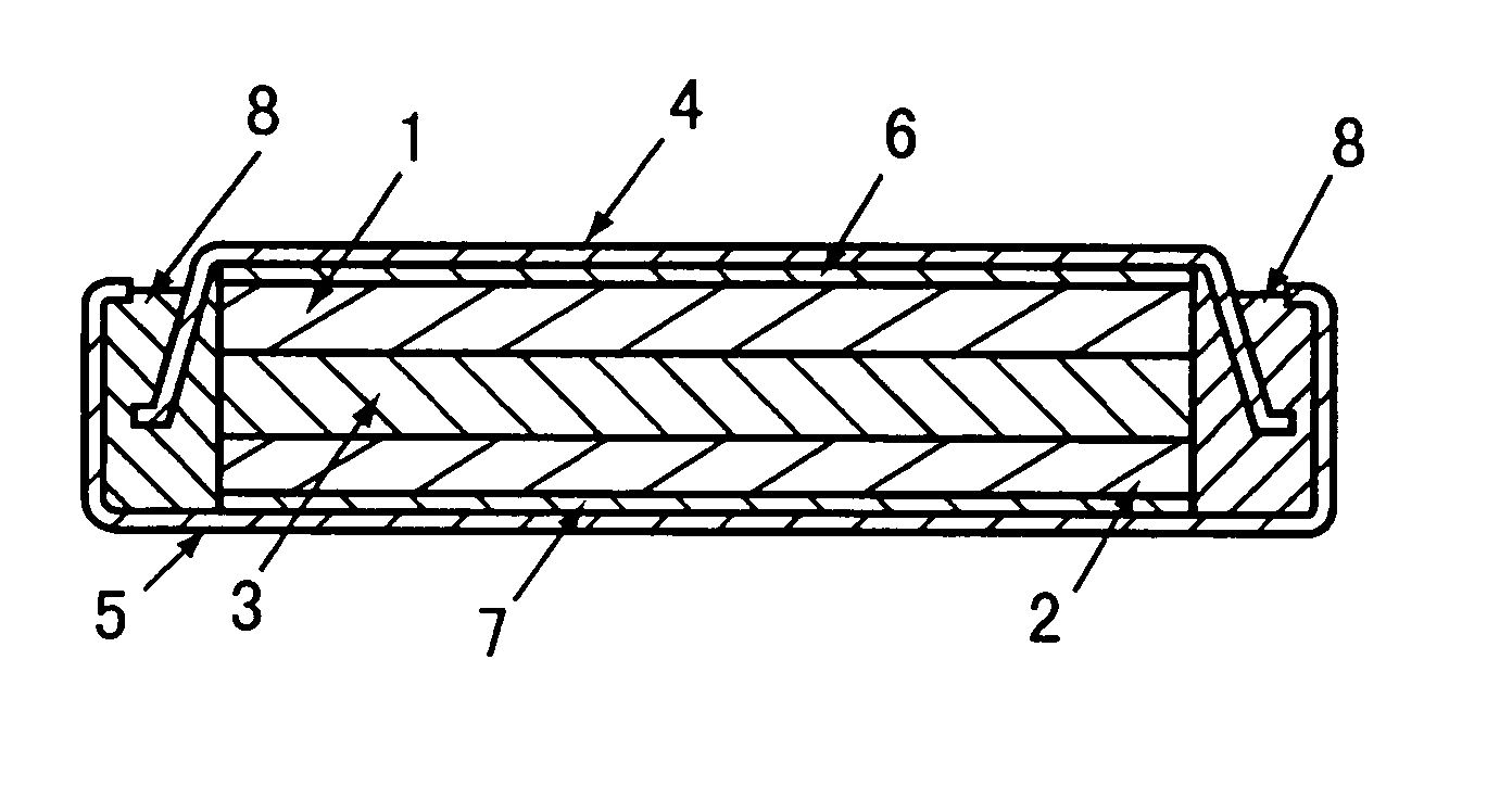
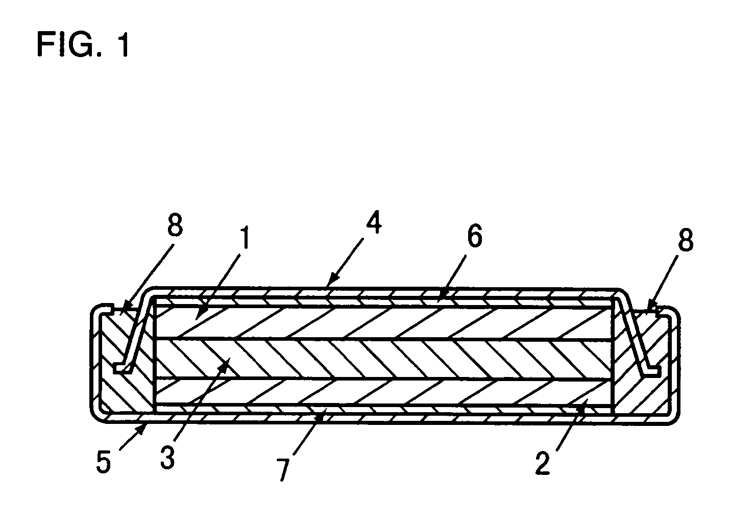
Image

Examples
experiment 1
[0049] (Fabrication of Negative Electrode)
[0050] 80.2 parts by weight of a silicon powder (99.9% pure) having a mean particle diameter of 3 μm, as active material particles, was mixed in an 8.6 wt. % N-methylpyrrolidone solution containing 19.8 parts by weight of polyamic acid (binder α1) as a binder to provide an anode mix slurry.
[0051] This anode mix slurry was coated on one surface (rough surface) of an electrolytic copper foil (35 μm thick) (current collector a1) having a surface roughness Ra of 0.5 μm, as a current collector, dried and then calendered. A 20 mm diameter disk was cut out from the coated copper foil, and then sintered by a heat treatment under argon atmosphere at 400° C. for 30 hours to provide a negative electrode. The sintered body (inclusive of the current collector) was 50 μm thick. Accordingly, the thickness of the active material layer was 15 μm, active material layer thickness / copper foil surface roughness was 30, and active material layer thickness / coppe...
experiment 2
[0065] A 33 μm thick, rolled copper foil (surface roughness Ra: 0.1 μm) was roughened at its surface by electrolytic copper plating to a surface roughness Ra of 0.5 μm. In Experiment 1, the resulting copper foil (current collector b1) was used in place of the electrolytic copper foil (current collector a1) with a surface roughness Ra of 0.5 μm. Otherwise, the procedure of Experiment 1 was followed to construct a battery B1. After the roughening treatment, the current collector b1 was 35 μm thick. In addition, a 33 μm thick, rolled copper alloy (Cu-0.03 wt. % Zr) foil (surface roughness Ra: 0.1 μm) was roughened at its surface by electrolytic copper plating to a surface roughness Ra of 0.5 μm. In Experiment 1, the resulting copper alloy foil (current collector a2) was used in place of the electrolytic copper foil (current collector a1) having a surface roughness Ra of 0.5 μm. Otherwise, the procedure of Experiment 1 was followed to construct a battery A2. After the roughening treatme...
experiment 3
[0066] In Experiment 1, a 35 μm thick electrolytic copper foil (current collector a3 or a4) composed of the same material as the current collector a1 and having a surface roughness Ra of 0.2 μm or 0.17 μm was used in place of the electrolytic copper foil (current collector a1) having a surface roughness Ra of 0.5 μm. Otherwise, the procedure of Experiment 1 was followed to construct batteries A3 and A4.
[0067] In Experiment 1, a 18 μm thick electrolytic copper foil (current collector a5 or a6) composed of the same material as the current collector al and having a surface roughness Ra of 0.5 μm or 0.2 μm was used in place of the current collector a1. Otherwise, the procedure of Experiment 1 was followed to construct batteries A5 and A6.
[0068] In Experiment 1, the current collector a4 was used, the loading of the active material was altered and the thickness of the active material layer was increased to 95 μm. Otherwise, the procedure of Experiment 1 was followed to construct a batte...
PUM
 Abstract
Description
Claims
Application Information