Electrode for lithium secondary battery and method for producing the same

a lithium secondary battery and electrode technology, applied in the direction of negative electrodes, cell components, coatings, etc., can solve the problems of deteriorating the charge-discharge cycle characteristics, large volume expansion and shrinkage with charge and discharge, and silicon use has not yet been commercialized, and achieve excellent charge-discharge cycle characteristics.

Inactive Publication Date: 2005-01-18
SANYO ELECTRIC CO LTD
View PDF5 Cites 19 Cited by
  • Summary
  • Abstract
  • Description
  • Claims
  • Application Information

AI Technical Summary

Benefits of technology

An object of the present invention is to provide an electrode for a lithium secondary battery capable of controlling diffusion of a current collector component and exhibiting an excellent charge-discharge cycle characteristics, and a method for producing the same.
According to the present invention, an interlayer containing Mo or W is provided between the current collector and the thin film of active material. With providing the interlayer, it is possible to suppress diffusion of a current collector component into the thin film appropriately, and thus prevent generation of an adverse effect due to excessive diffusion of the current collector component.
The component of the interlayer is not limited to Mo and W, but substantially the same effect can be obtained by use of at least one kind of metal selected from the group consisting of magnesium (Mg), aluminum (Al), titanium (Ti), vanadium (V), chromium (Cr), manganese (Mn), iron (Fe), cobalt (Co), nickel (Ni), zinc (Zn), germanium (Ge), zirconium (Zr), niobium (Nb), molybdenum (Mo), ruthenium (Ru), silver (Ag), indium (In), tin (Sn), antimony (Sb), tantalum (Ta), tungsten (W) and lead (Pb), an alloy containing at least one kind of metal selected from the above group as a main component, or an oxide, nitride or carbide of any kind of metal selected from the above group.
The surface of the interlayer in contact with the thin film is preferably roughened. With this roughened surface, the adhesion between the interlayer and the active material thin film is further improved. The surface of the interlayer can be roughened in correspondence with a roughened surface of the current collector. In other words, the surface of the current collector is roughened, and the interlayer is formed on the current collector so that the surface of the interlayer is roughened in correspondence with the surface of the current collector.
In the active material thin film according to the present invention, preferably, gaps are formed in the thickness direction due to volume expansion and shrinkage of the active material with charge-discharge reaction, and the thin film is divided into columns. By dividing into columns due to gaps formed in the thickness direction, spaces are formed around the columnar portions. Therefore, these spaces can accommodate volume expansion and shrinkage with charge-discharge reaction, generation of stress in the thin film can be prevented. This makes it possible to prevent pulverization of the thin film and separation of the thin film from the current collector, and thus improve the charge-discharge cycle characteristics.

Problems solved by technology

However, since silicon stores lithium by forming an alloy with lithium, the volume greatly expands and shrinks with charge and discharge.
This causes problems such as pulverization of the active material and separation of the material from a current collector, and thus deteriorates the charge-discharge cycle characteristics.
For this reason, use of silicon has not yet been commercialized.
However, since the diffusion coefficient of copper in silicon or germanium is significantly large, an excessive amount of the current collector component may diffuse in the thin film forming an alloy depending on the thin film formation conditions and the type of the current collector used.
In such a case, the charge-discharge cycle characteristics may be deteriorated.

Method used


Image

  • Electrode for lithium secondary battery and method for producing the same
  • Electrode for lithium secondary battery and method for producing the same
  • Electrode for lithium secondary battery and method for producing the same

Examples


experiment 1

(Experiment 1)

[Production of Electrodes a1 and a2]

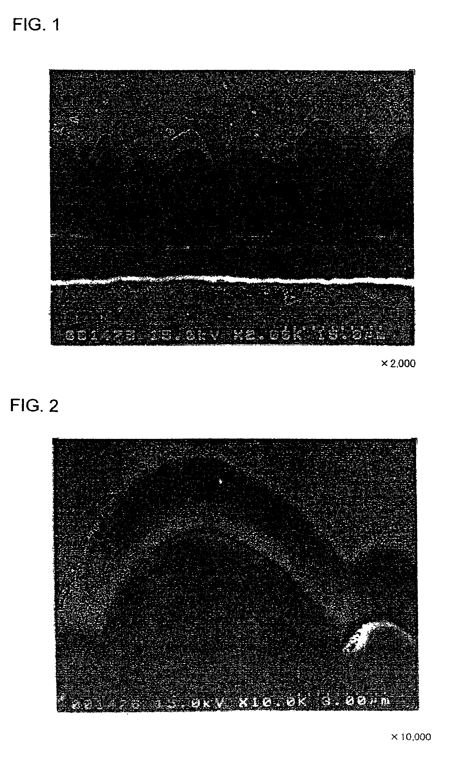
An Mo layer and a W layer having a thickness of 0.1 μm as an interlayer were respectively formed on the roughened surface of the electrolytic copper foil (thickness: 18 μm) having a surface roughness Ra of 0.188 μm in an argon (Ar) atmosphere by RF sputtering. The thin film formation was performed under the conditions of an RF power of 200 W, an Ar gas flow of 60 sccm, a chamber inner pressure of 0.1 Pa, and room temperature (not heated) as the substrate temperature.

Thereafter, a microcrystalline silicon thin film was formed on each of the Mo layer and the W layer by a CVD method, using silane (SiH4) gas as the material gas and hydrogen gas as the carrier gas. The thin film formation was performed under the conditions of an SiH4 flow of 10 sccm, an H2 gas flow of 200 sccm, a substrate temperature of 180° C., a reaction pressure of 40 Pa, and an RF power of 555W.

The microcrystalline silicon thin film was deposited to a thickness of 2 ...

experiment 2

(Experiment 2)

[Production of Electrodes c1 and c2]

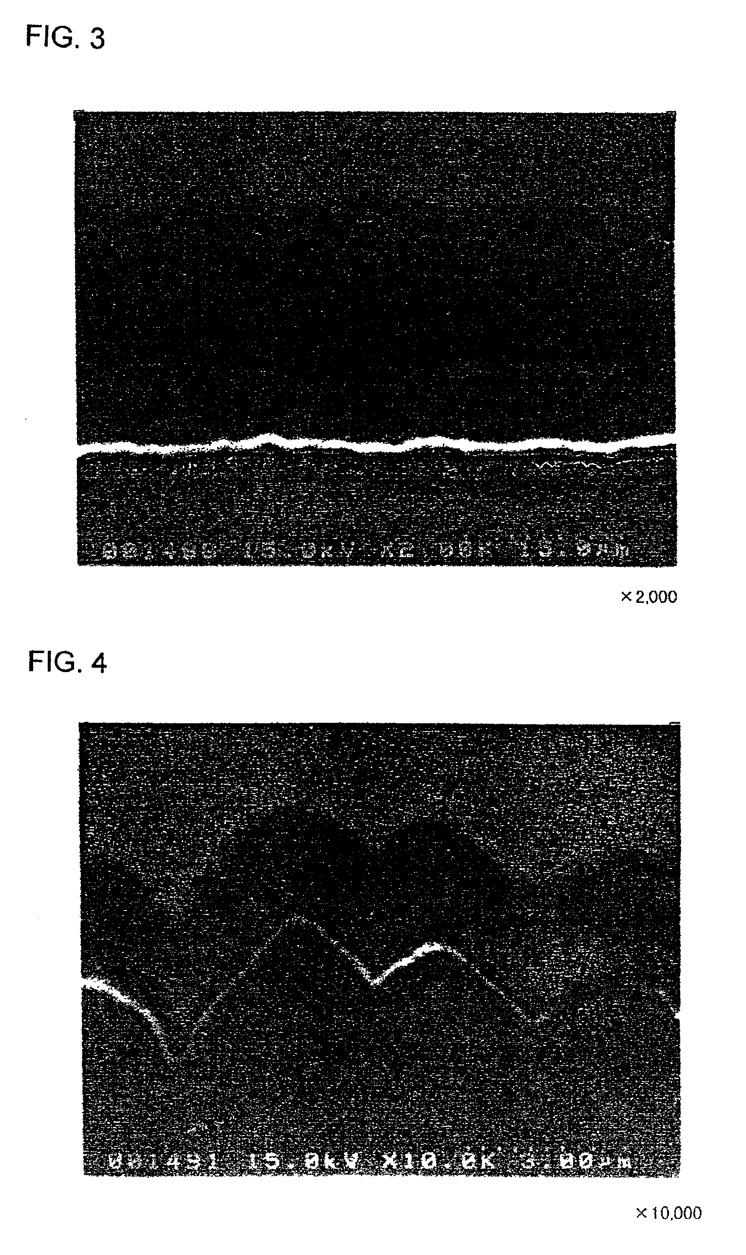
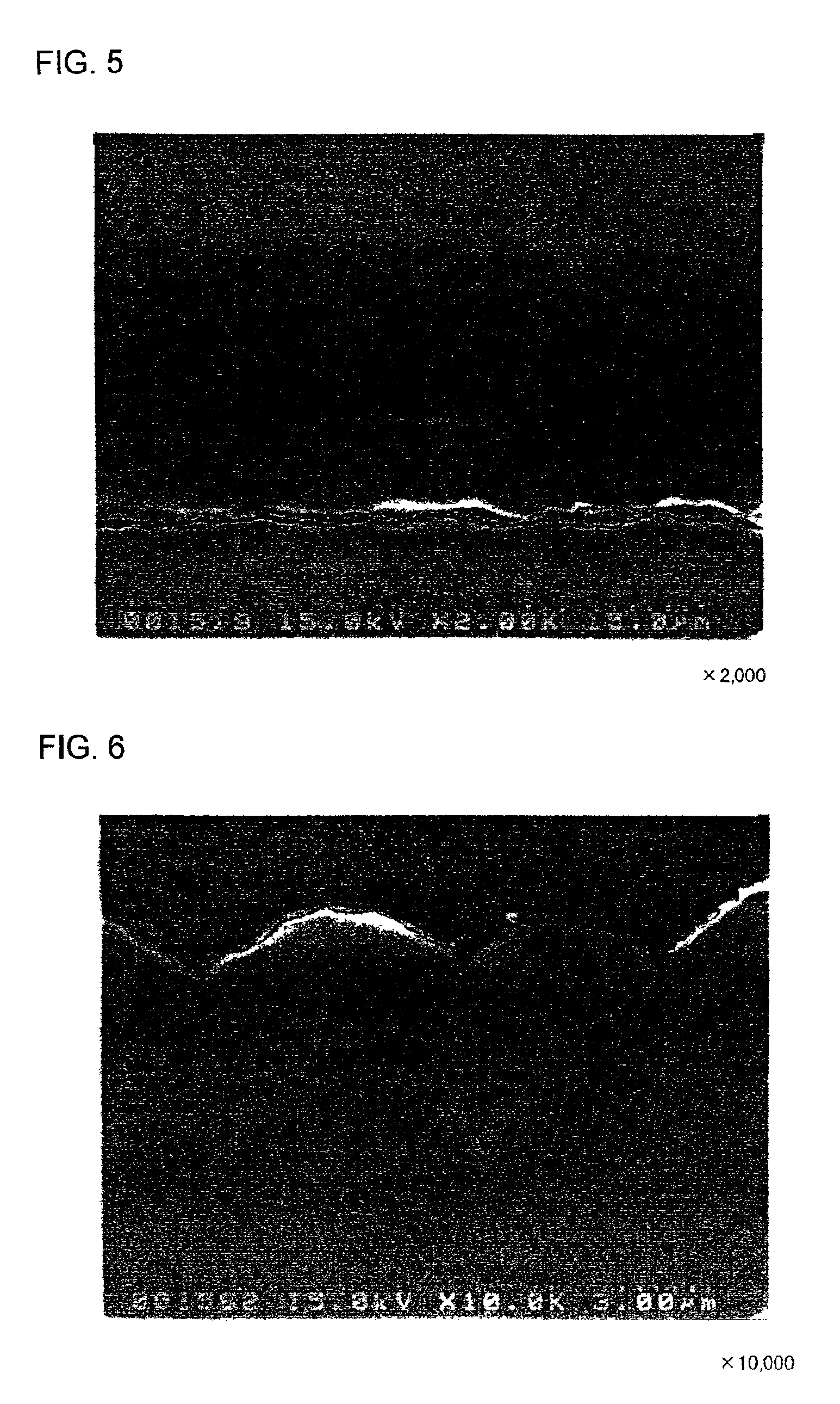
An Mo layer and a W layer as the interlayer were respectively formed on rolled copper foil (thickness: 18 μm) having a surface roughness Ra of 0.037 m under the same conditions as those in the formation of the electrodes a1 and a2.

Thereafter, a microcrystalline silicon thin film was formed on each of the Mo and W layers under the same conditions as those in the formation of the electrodes a1 and a2. The resultant silicon thin film was cut into a 2 cm×2 cm piece together with the rolled copper foil, to obtain an electrode c1 with the Mo interlayer and an electrode c2 with the W interlayer.

[Production of Electrode d1]

An electrode d1 was produced in the same manner of the electrodes c1 and c2, except that a microcrystalline silicon thin film was directly formed on the rolled copper foil with no Mo or W layer therebetween.

[Measurement of Charge-discharge Cycle Characteristics]

Using the electrodes c1, c2 and d1 respectively as the working...


PUM

PropertyMeasurementUnit
thicknessaaaaaaaaaa
surface roughness Raaaaaaaaaaa

Abstract

The electrode for a lithium secondary battery includes: a current collector; an interlayer containing Mo or W provided on the current collector; and a thin film composed of active material capable of lithium storage and release deposited on the interlayer.

Description

BACKGROUND OF THE INVENTION1. Field of the InventionThe present invention relates to an electrode for a lithium secondary battery and a method for producing the same.2. Related ArtIn recent years, development of lithium secondary batteries has been actively made. The battery properties of a lithium secondary battery, such as the charge-discharge voltages, the charge-discharge cycle life characteristics and the storage property, are greatly influenced by the electrode active material used.Among electrode active materials capable of lithium storage and release, silicon which is a material storing lithium by being alloyed with lithium, has been examined in various aspects because it has a large theoretical capacity. However, since silicon stores lithium by forming an alloy with lithium, the volume greatly expands and shrinks with charge and discharge. This causes problems such as pulverization of the active material and separation of the material from a current collector, and thus dete...

Claims


Application Information

Patent Timeline
Patent Type & Authority Patents(United States)
IPC IPC(8): B05D5/12B23P13/00H01M4/58H01M4/72H01M4/66H01M4/13H01M4/139H01M4/38H01M10/052
CPCH01M4/13H01M4/139H01M4/38H01M4/661H01M4/667H01M4/664Y10T29/10H01M10/052H01M2004/027Y02E60/122H01M4/386Y02E60/10
Inventor YAGI, HIROMASATARUI, HISAKI
Owner SANYO ELECTRIC CO LTD
Why Eureka
Try Eureka