Communication apparatus

a technology of communication apparatus and communication circuit, which is applied in the direction of transmission monitoring, pulse technique, modulation, etc., can solve the problems of inability to stabilize power control, increase the cost of devices, and inability to transmit power

Inactive Publication Date: 2005-11-03
KOKUSA ELECTRIC CO LTD
View PDF1 Cites 60 Cited by
  • Summary
  • Abstract
  • Description
  • Claims
  • Application Information

AI Technical Summary

Benefits of technology

[0038] Therefore, for example, even in case that transmission power of each channel at an antenna end fluctuates due to setup frequency of an antenna sharing device, stable power control is possible. Then, it is possible to realize effective automatic power control (APC).
[0051] Therefore, for example, it does not take so much time until a wave detection level becomes stable, and it is applicable to the APC loop which is locked at high speed, and there is no-need to change a reference voltage of APC in tune with a type of modulation. Then, it is possible to realize effective automatic power control (APC).
[0053] In addition, as the modulating signal level changing unit, various ones may be used, and for example, it is possible to configure it by a variable amplifier which amplifies a signal with a variable gain (amplification amount), and in sum, increases a level of a signal, a variable attenuator which attenuates a signal with a variable gain (attenuation amount), and in sum, reduces a level of a signal, and so on.
[0059] As described above, according to the communication apparatus which relates to the first invention, a level of a signal which becomes, as to each of plural channels, a transmission object of each channel is changed, and filtering is applied to a signal of each channel, of which level was changed by a filtering characteristic for allowing a passage of a frequency component of each channel, and signals of the plural channels for which the filtering was carried out are coupled, and the coupled signal is transmitted through the antenna by wireless, and on the occasion of this, a part of the coupled signal, which is outputted to the antenna, is divided into a plurality of signals, and as to each of the plural channels, filtering is applied to each divided signal, by a filtering characteristic which is identical to the above-described filtering characteristic, and a level of a signal of each channel, which was obtained by the filtering, is detected, and on the basis of the detected level of a signal of each channel, a mode of changing a level of a signal which becomes a transmission object of each channel is controlled, and therefore, for example, even in case that transmission power of each channel at an antenna end fluctuates due to setup frequency of an antenna sharing device, stable power control is possible, and it is possible to realize effective automatic power control (APC).
[0060] In addition, according to the communication apparatus which relates to the second invention, on the occasion of changing a level of a modulating signal which becomes a transmission object, a level of a modulating signal is detected before its level is changed, and the detected level and a predetermined value based on a transmission level which becomes a target independently from a modulation system are synthesized, and in addition, a level of a modulating signal is detected after its level was changed, by an identical detection characteristic to that of the above-described level detection, and on the basis of a difference of the above-described synthesis result and the detected level, a mode of changing a level of a modulating signal which becomes a transmission object is controlled, and therefore, for example, it does not take so much time until a wave detection level becomes stable, and it is also applicable to an APC loop which is locked at high speed, and in addition, there is no need to change a reference voltage of APC in tune with a type of modulation, and it is possible to realize effective automatic power control (APC).

Problems solved by technology

However, in the wireless communication apparatus shown in FIG. 7, there are problems as follows.
For example, conceivable is a method for carrying out output correction depending on elongation frequency, but this requires a device for monitoring frequency of all channels, and therefore, a device cost increases, which is not preferable.
In this manner, in the APC system shown in FIG. 7, there is such a problem that transmission power of each channel at the antenna 79 end fluctuates due to setup frequency of the antenna sharing device, and stable power control is impossible.
However, it takes time until a wave detection level becomes stable, and therefore, there is such a problem that it is not adequate to the APC loop which is locked at high speed.
However, a wave detection level changes due to a modulation wave form, and therefore, there is such a problem that there is a necessity to change a reference voltage of APC (output voltage from the reference voltage source 106) in tune with a type of modulation, by disposing a correction coefficient with respect to each type of modulation (modulation system).
In addition, there is a limit in the number of correction coefficients, and therefore, there is a limit in types of modulations for which APC is available, and on this account, for example, there is such a problem that it becomes impossible to control even if the number of types of modulations increases in the future.
In addition, in order to setup the correction coefficient, conceivable is such a configuration that, for example, a resistor volume and a ROM (Read Only Memory) table etc. are used, but there is such a problem that it is directly linked to cost rise.
In addition, as to which type of modulation responsive signal is outputted, an instruction signal from the modulating signal generator 101 becomes necessary, and therefore, there is such a problem that control becomes complex.

Method used


Image

  • Communication apparatus
  • Communication apparatus
  • Communication apparatus

Examples


embodiment 1

[0074] A first embodiment of the invention will be described.

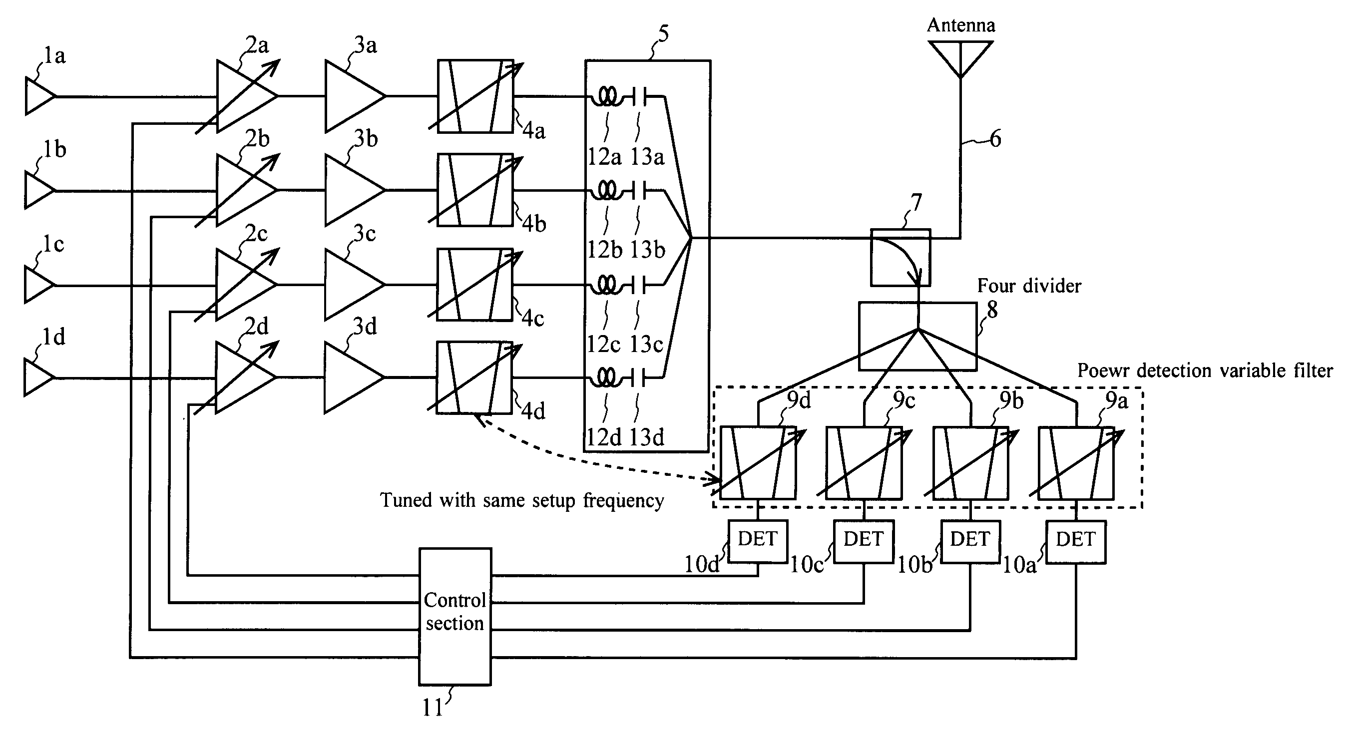
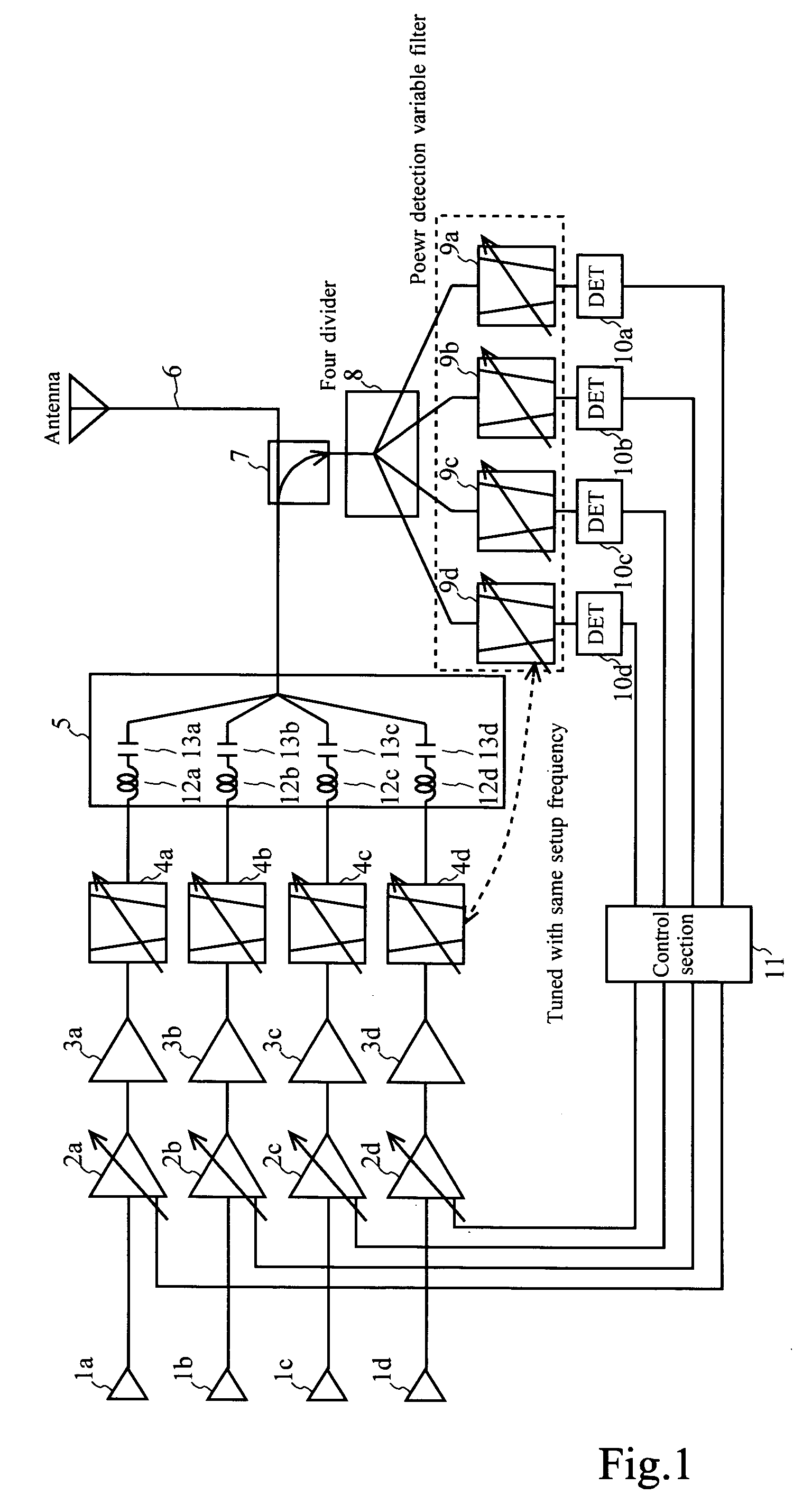
[0075]FIG. 1 shows a configuration example of a transmitter which is equipped with a 4 channel (ch) antenna sharing device, as a configuration example of a wireless communication apparatus in this embodiment.

[0076] The wireless communication apparatus in this embodiment is equipped with four pieces of input terminals 1a to 1d, four pieces of variable amplifiers 2a to 2d, four pieces of power amplifiers (PA) 3a to 3d, four pieces of variable filters (frequency variable filters) 4a to 4d which are configured by for example, band pass filters (BPF), a coupling circuit 5 which has four sets of coils 12a to 12d and capacitors 13a to 13d, an antenna 6, a directional coupler 7, a four divider 8, four pieces of power detection variable filters (frequency variable filters) 9a to 9d which are configured by for example, band pass filters (BPF), four pieces of wave detectors 10a to 10d, and a control section 11.

[0077] One example o...

embodiment 2

[0110] A second embodiment of the invention will be described.

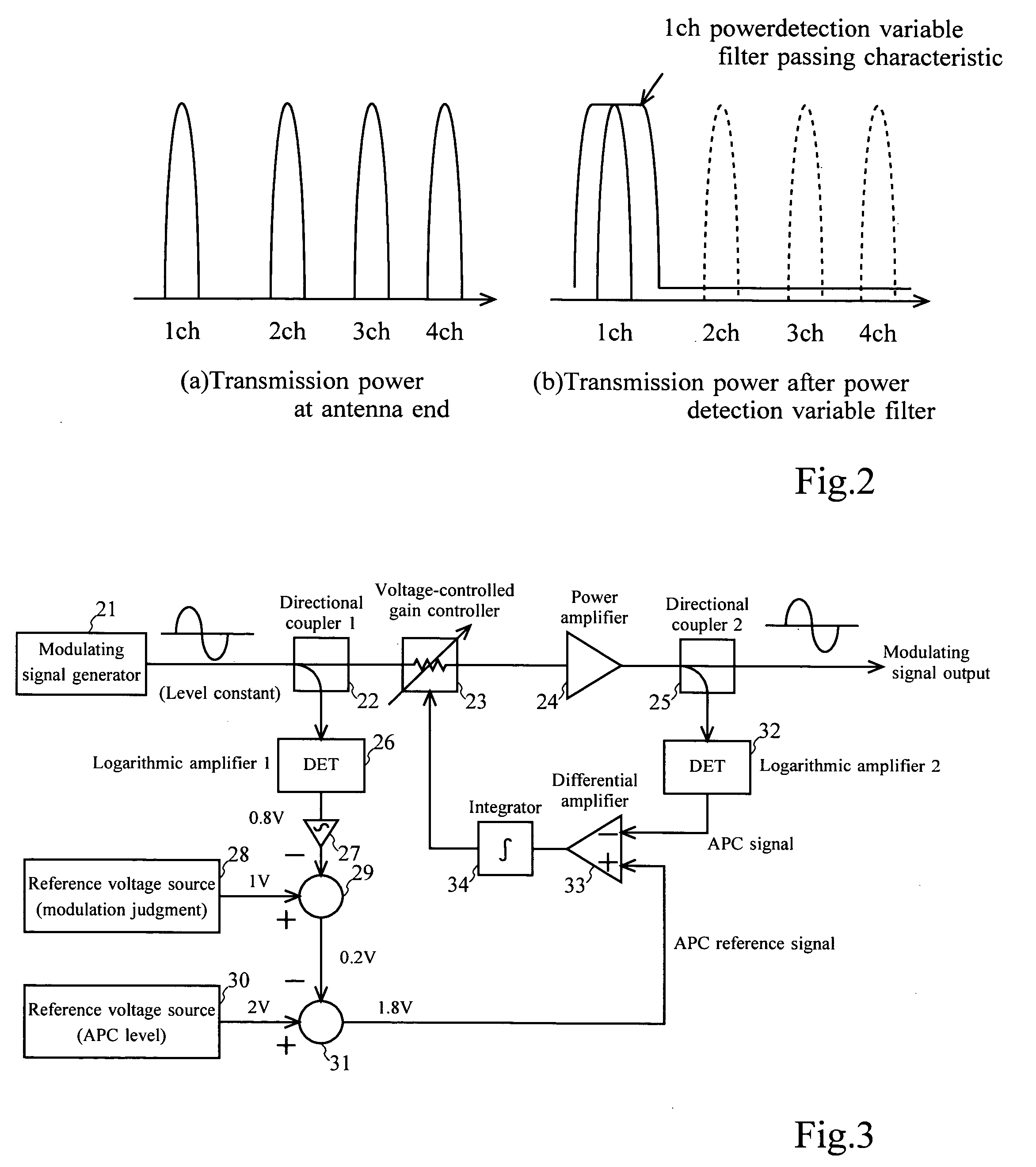
[0111]FIG. 3 shows a configuration example of a wireless communication apparatus of this embodiment.

[0112] The wireless communication apparatus in this embodiment is equipped with a modulating signal generator 21, a first directional coupler 22, a voltage-controlled gain controller 23, a power amplifier (PA) 24, a second directional coupler 25, a first logarithmic amplifier (wave detector) 26, a filter 27 which is for example, a low pass filter (LPF), a first reference voltage source (modulation judgment) 28, a first adder 29, a second reference voltage source (APC level) 30, a second adder 31, a second logarithmic amplifier (wave detector) 32, a differential amplifier 33, and an integrator 34.

[0113] Here, as the first logarithmic amplifier 26 and the second logarithmic amplifier 32, they are configured by wave detectors which have the same wave detection characteristic.

[0114]FIG. 4A shows one example of an input-outp...


PUM


Abstract

In a communication apparatus, effective automatic power control (APC) is realized. Transmission object signal level changing units change a level of a transmission object signal of each channel, and transmission filter units carry out filtering for a signal of each channel after its level was changed with a characteristic for allowing a passage of a frequency component of each channel, and a transmission signal coupling unit couples signals of plural channels after the filtering was carried out, and an antenna transmits a coupled signal by wireless, and coupled signal dividing units divide a part of the coupled signal into a plurality of signals, and level detection filter units carry out filtering for each divided signal with an identical characteristic to the above-described characteristic, and signal level detecting units detect a level of a signal of each channel after the filtering was carried out, and a transmission object signal level change mode controlling unit controls a level change mode of a transmission object signal of each channel on the basis of the detection result.

Description

BACKGROUND OF THE INVENTION [0001] 1. Field of the Invention [0002] This invention relates to a communication apparatus which communicates a signal, and in particular, relates to a communication apparatus which realizes effective automatic power control (APC). [0003] 2. Description of the Relevant Art [0004] A first background technology will be described. [0005] Meanwhile, a matter, which will be described here, does not necessarily mean that every technologies are conventional technologies. [0006]FIG. 6 shows a configuration example of a wireless communication apparatus which adopted an one channel (ch) APC system. [0007] The wireless communication apparatus in this example is equipped with an input terminal 61, a variable amplifier 62, a power amplifier (PA) 63, a filter 64, an antenna 65, a directional coupler 66, a wave detector 67, a comparator 68, and a loop filter 69. [0008] In the wireless communication apparatus of this example, power detection is carried out at the antenn...

Claims


Application Information

Patent Timeline
Patent Type & Authority Applications(United States)
IPC IPC(8): H03F1/06H03F3/21H03F3/24H03G3/20H03G3/30H03K19/00H04B1/02H04B1/04
CPCH03F1/0205H03F3/211H03G3/3042H03F2200/78H03F3/24
Inventor HIRANO, TAKAYUKISUZUKI, YASUHIKO
Owner KOKUSA ELECTRIC CO LTD
Why Eureka
Try Eureka