
Prosthetic knee

a knee joint and prosthesis technology, applied in the field of knee joint prosthesis, can solve the problem that the design cannot accommodate valgus-varus motion, and achieve the effect of providing stability

Inactive Publication Date: 2005-11-03
BUECHEL PAPPAS TRUST
View PDF18 Cites 58 Cited by
  • Summary
  • Abstract
  • Description
  • Claims
  • Application Information

AI Technical Summary

Benefits of technology

[0012] The invention relates to a hinged knee prosthesis with a condylar bearing. The prosthesis includes a femoral component for mounting to the resected distal end of the femur, a tibial component for mounting to the resected proximal end of the tibia, a bearing for disposition between the femoral and tibial components and a hinge assembly for providing stability during articulation between the femoral and tibial components. The prosthesis may further include a patellar component.
[0013] The hinged knee prosthesis of the subject invention differs from prior art hinged knee prostheses by providing patellofemoral articulating surfaces that are distinct from the tibiofemoral articulating surfaces. The patellofemoral articulation may be similar or identical to that of prior art knee prostheses and may include a compound curve as the articulating surface on the femoral component. However, the tibiofemoral articulating surface is configured for congruent contact over a larger range of motion than is available for knee prosthesis without distinct tibiofemoral and patellofemoral articulating surface. Preferably the congruent contact for the tibiofemoral articulation extends for substantially the entire range of motion. This provides a significant advantage of reduced wear, as compared to prior art prosthetic knees, including prior art hinged knee prostheses.
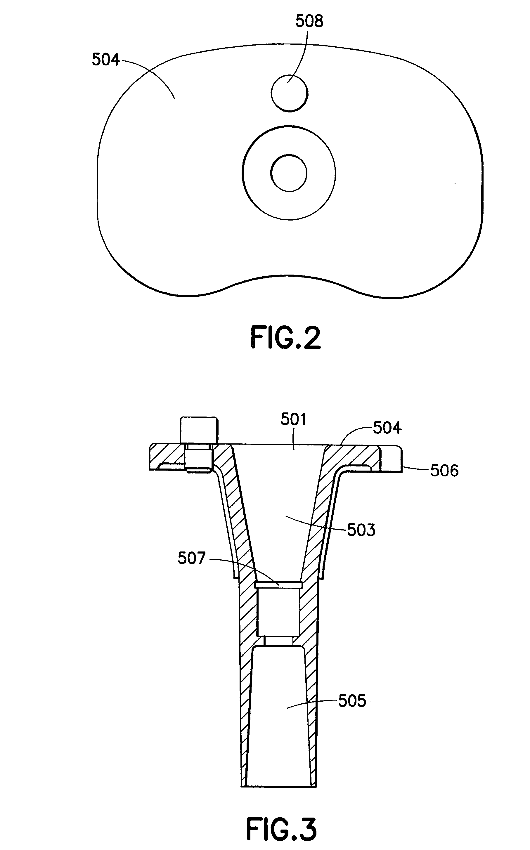
[0016] The bearing of the prosthetic knee includes a plastic cone that can be mounted in the conical hole of the tibial component so that the bearing can rotate relative to the tibial component. The cone of the bearing preferably includes axial separation means for preventing axial separation or dislocation of the bearing from the tibial component. Thus, the prosthetic knee can provide dislocation resistance at least as good as prior art hinged prostheses, but with a shorter cone and hence less bone removal. The axial separation means may include a groove in the cone of the bearing that will align with the groove in the conical hole of the tibial component when the cone of the bearing is mounted in the conical hole of the tibial component. A snap ring may be engageable in the aligned grooves of the conical hole in the tibial component and in the cone of the bearing. The snap ring prevents the bearing from moving proximally and out of the conical hole in the tibial component. However, the snap ring permits the cone of the bearing to rotate relative to the tibial component. Hence, rotational mobility for the bearing is permitted, but dislocation of the bearing is prevented. Other connections that permit rotation but not separation can be provided
[0017] The bearing further includes an inferior bearing surface for bearing engagement on the superior tibial surface of the tibial component. Means may be provided for limiting rotational movement of the bearing on the superior tibial surface. For example, the inferior surface of the bearing may be formed with an arcuate groove, and a pin may project from the superior surface of the tibial component for engagement in the groove of the bearing. Thus, the angular extend of the groove in the bearing will limit the range of pivotal movement of the bearing relative to the tibial component. The bearing further includes a superior condylar bearing region for articular bearing engagement with the femoral component. The bearing further include a hole extending from the proximal or superior end to or towards the distal end. Lower portions of the hole in the bearing may be conically tapered.
[0020] The congruent articular bearing engagement of the tibiofemoral articular surface of the femoral component with the condylar bearing region on the superior surface of the bearing provides congruency through virtually all ranges of motion from a slightly hyperextended condition to deep flexion. Thus, the prosthetic knee of the subject invention provides congruent contact during many high load activities, such as stair climbing and descent and arising from a chair. Additionally, the prosthetic knee of the subject invention provides very good resistance to valgus-varus moments. Furthermore, the engagement of the cone of the bearing in the conical hole of the tibial component resists dislocation and the engagement of the stop pin with the groove in the inferior bearing surface of the bearing controls and limits the range of permissible rotation of the tibia relative to the femur. Thus, the prosthetic knee of the subject invention is well suited for those situations where the ligaments are not present or are ineffective.

Problems solved by technology

However, such a design would not accommodate valgus-varus motion, which is motion in a generally medial to lateral direction.

Method used


Image

  • Prosthetic knee
  • Prosthetic knee
  • Prosthetic knee

Examples


Embodiment Construction

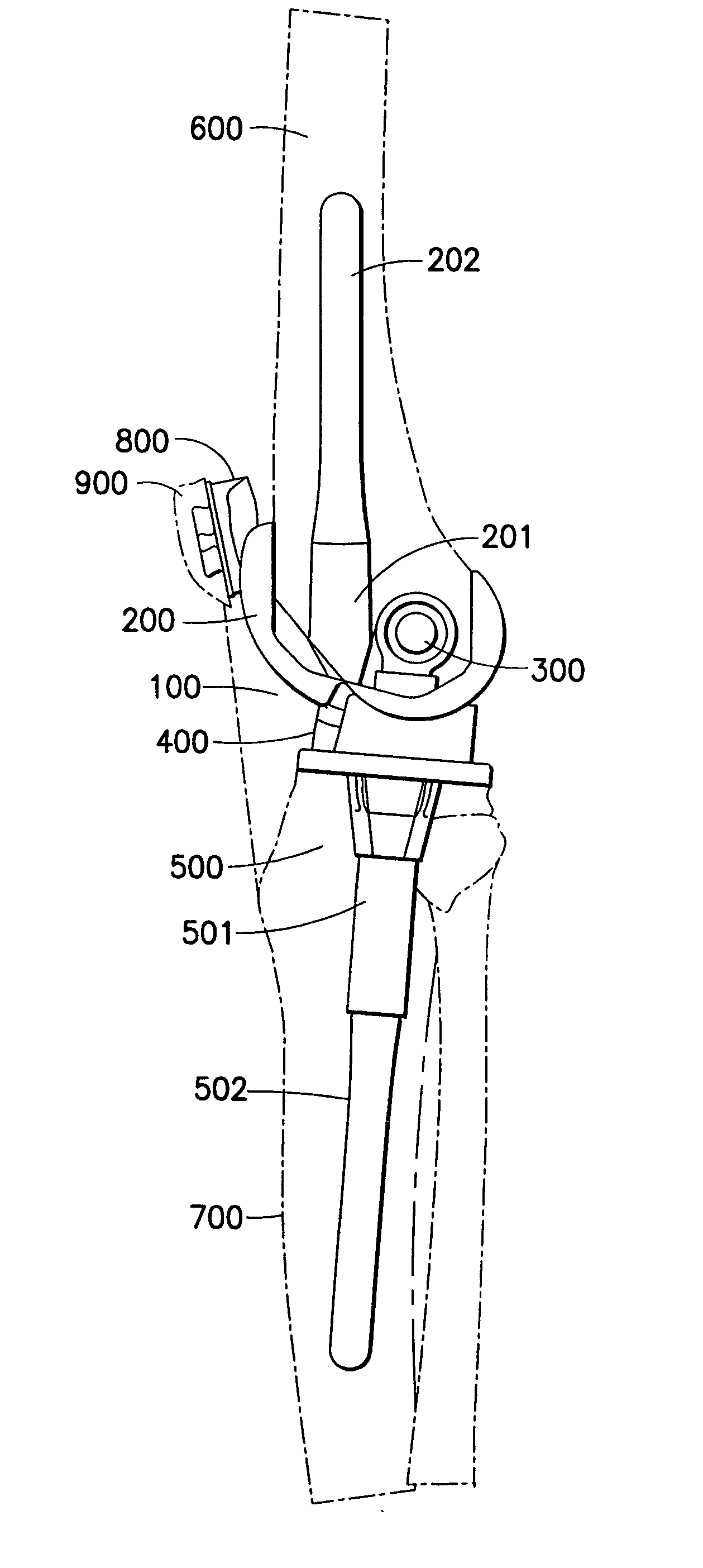
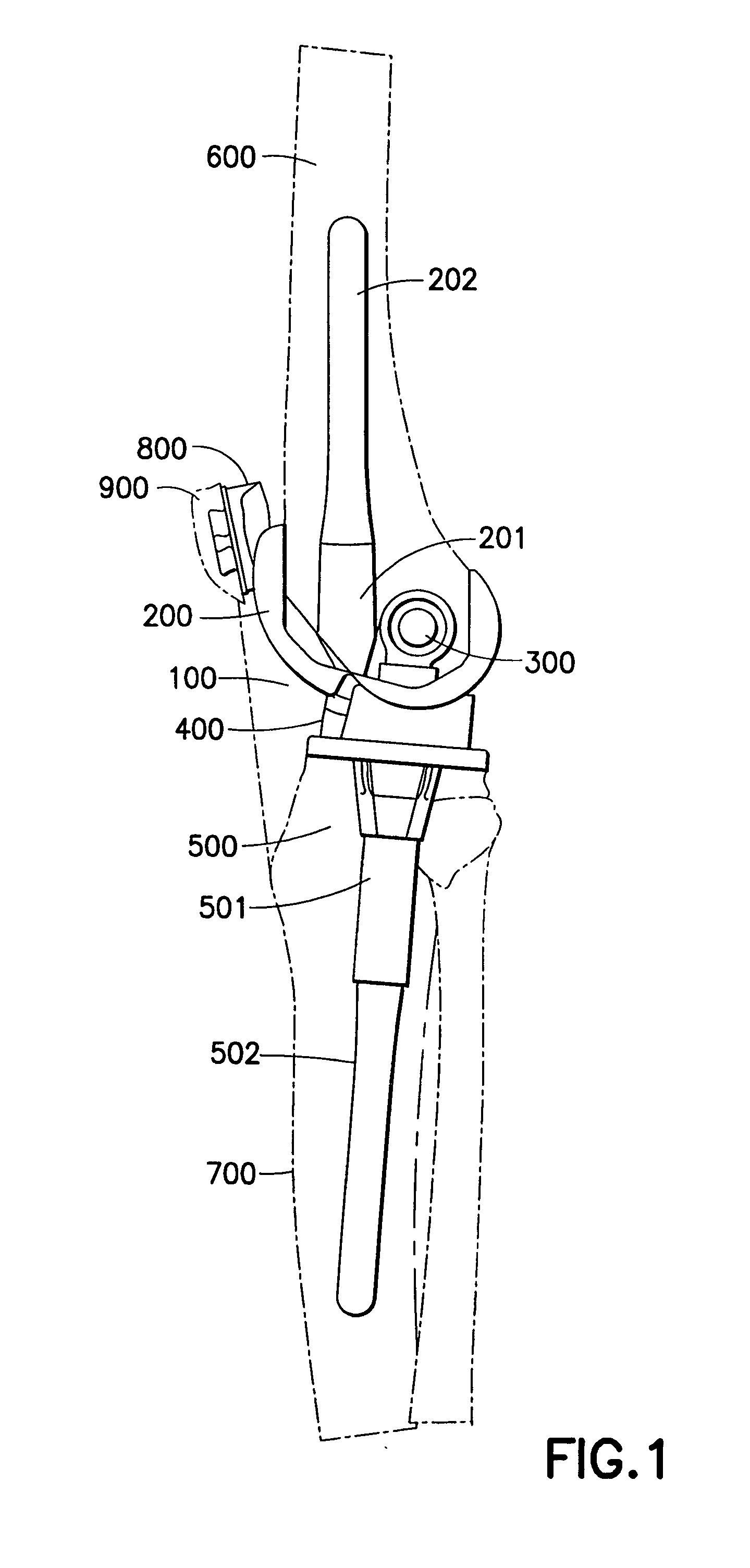
[0044] A hinged knee prosthesis in accordance with the invention is identified generally by the numeral 100 in FIGS. 1 and 19-23. The knee prosthesis 100 includes a femoral component identified generally by the numeral 200 in FIG. 1. The femoral component 200 is configured for mounting to the resected distal end of the natural femur 600. The femoral component 200 is configured for articulation relative to an assembly that includes a hinge subassembly 300, a plastic bearing 400 and a tibial component 500. The tibial component 500 is configured for mounting in the resected proximal end of the natural tibia 700. The prosthesis 100 may further include a patellar component 800 that may be implanted in the natural patella 900.

[0045] The tibial component 500 includes a body 501 and a stabilizing rod 502 as shown in FIG. 1. Both the body 501 and the stabilizing rod 502 are formed from a metallic material that will provide appropriate strength and biocompatibility. A preferred tibial compon...


PUM

PropertyMeasurementUnit
rotationaaaaaaaaaa
flexion anglesaaaaaaaaaa
rotational movementaaaaaaaaaa

Abstract

A hinged knee prosthesis includes a femoral component with a tibiofemoral articular surface that is distinct from the patellofemoral articulating surface. Fully congruent tibiofemoral articulation is provided for virtually all flexion angles. Additionally, the bearing is capable of at least limited axial rotation relative to the tibial component but is restrained against dislocation. Accordingly, dislocation is much less likely even n those situations where collateral ligaments are insufficient.

Description

[0001] This application claims priority on U.S. Provisional Patent Appl. No. 60 / 566,214, filed Apr. 28, 2004.BACKGROUND OF THE INVENTION [0002] 1. Field of the Invention [0003] The invention relates to a knee joint prosthesis, and particularly a hinged knee joint prosthesis. [0004] 2. Description of the Related Art [0005] A natural knee joint includes the distal end of the femur with articular cartilage, the proximal end of the tibia with articular cartilage and a meniscus between the femur and tibia. The femur and the tibia are held in a proper relationship to the meniscus by ligaments. These stabilizing ligaments include the posterior cruciate ligament, the anterior cruciate ligament and collateral ligaments. [0006] The condyles at the distal end of the femur define compound curves. Hence, the degree of congruency between the condyles of the natural femur and the superior surface of the meniscus varies at different degrees of flexion. Flexion of the knee causes the tibia to rotate...

Claims


Application Information

Patent Timeline
Patent Type & Authority Applications(United States)
IPC IPC(8): A61F2/00A61F2/38
CPCA61F2/385A61F2/3877A61F2002/30505A61F2310/0088A61F2310/00023A61F2310/00029A61F2220/0025
Inventor PAPPAS, MICHAEL J.BUECHEL, FREDERICK F.
Owner BUECHEL PAPPAS TRUST
Learn More