Identity verification method using a central biometric authority

a biometric authority and identity verification technology, applied in the direction of public key infrastructure trust models, instruments, digital transmission, etc., can solve the problems of inability for users to remember or input long keys, preventing the success of brute force attempts, and compromising secret codes by brute force attacks, etc., to achieve the effect of improving the performance of an identity verification system

Inactive Publication Date: 2005-11-10
FUSIONARC
View PDF59 Cites 117 Cited by
  • Summary
  • Abstract
  • Description
  • Claims
  • Application Information

AI Technical Summary

Benefits of technology

[0014] It is, therefore, a primary object of the present invention to provide a method capable of impro...

Problems solved by technology

It is not feasible, however, for a user to remember or input a long key, e.g., 64 character or longer, when the user wants to send or receive a message.
Unfortunately, many times this leads to people writing down the secret information, making it accessible to fraud perpetrators.
Also brute force attacks can compromise secret codes.
Long codes, mixing letters and numbers and frequent changing of codes can prevent the success of brute force attempts.
If the private key is compromised by one of the various techniques, then it is no longer possible to ensure that information is kept confidential and unchanged.
That is, the sender is not assured that the intended receiver is reading the message and the receiver is not assured that the intended sender sent the message.
There are myriad problems with one party relying on the other to use a biometric system to secure the private key.
Furthermore, there is no quality control over enrollment.
That is, there is no way to ensure that samples submitted during enrollment belong to a claimed enrollee.
There is currently no infrastructure for interpreting the verification score of each of these vendors.
As such, if the receiver learns that the sender is verified on a biometric system from a vendor with a score of 75, they would have difficulty in determining if this was a good match.
Finally, there is no way for a sen...

Method used


Image

  • Identity verification method using a central biometric authority
  • Identity verification method using a central biometric authority
  • Identity verification method using a central biometric authority

Examples


first embodiment

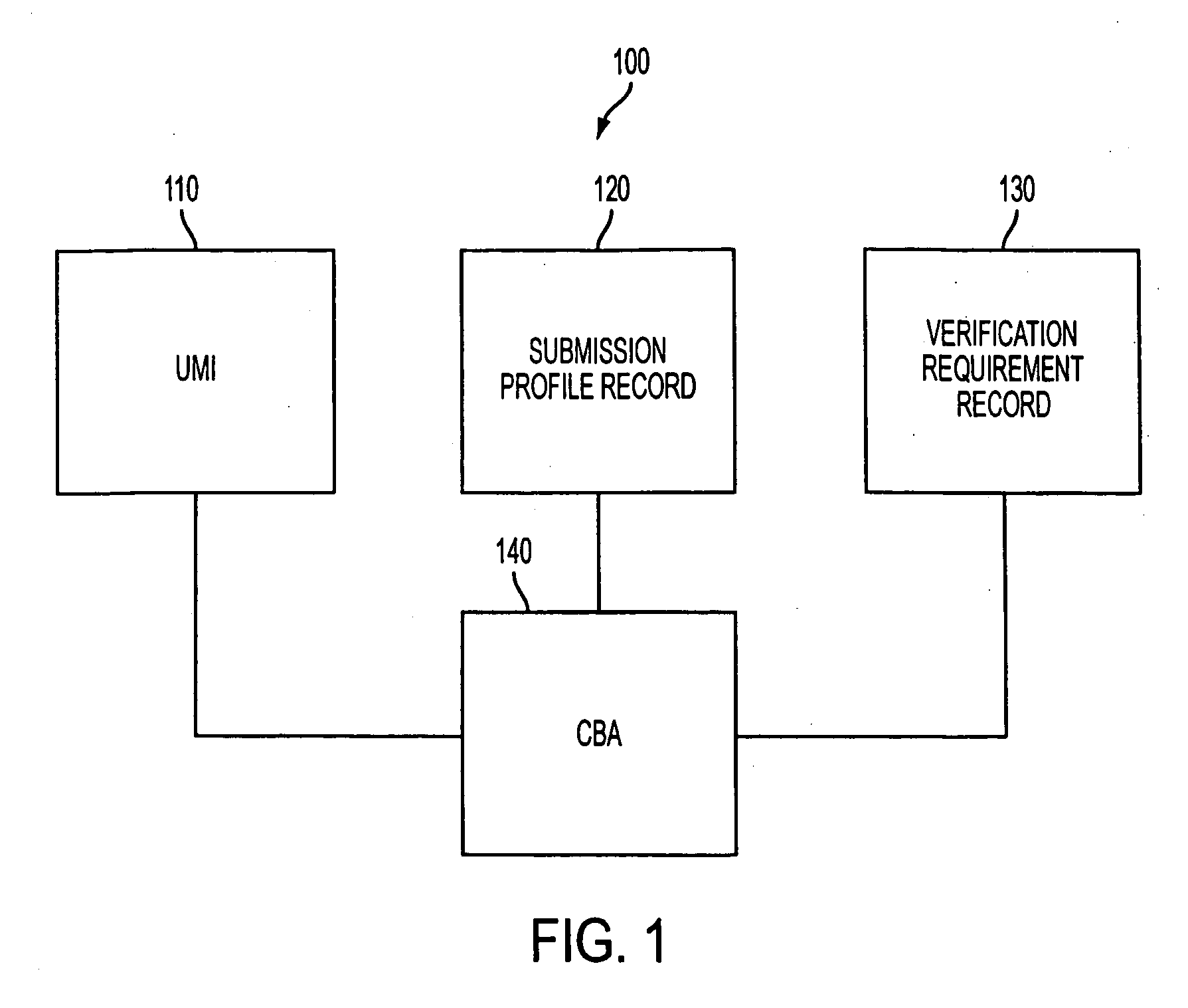
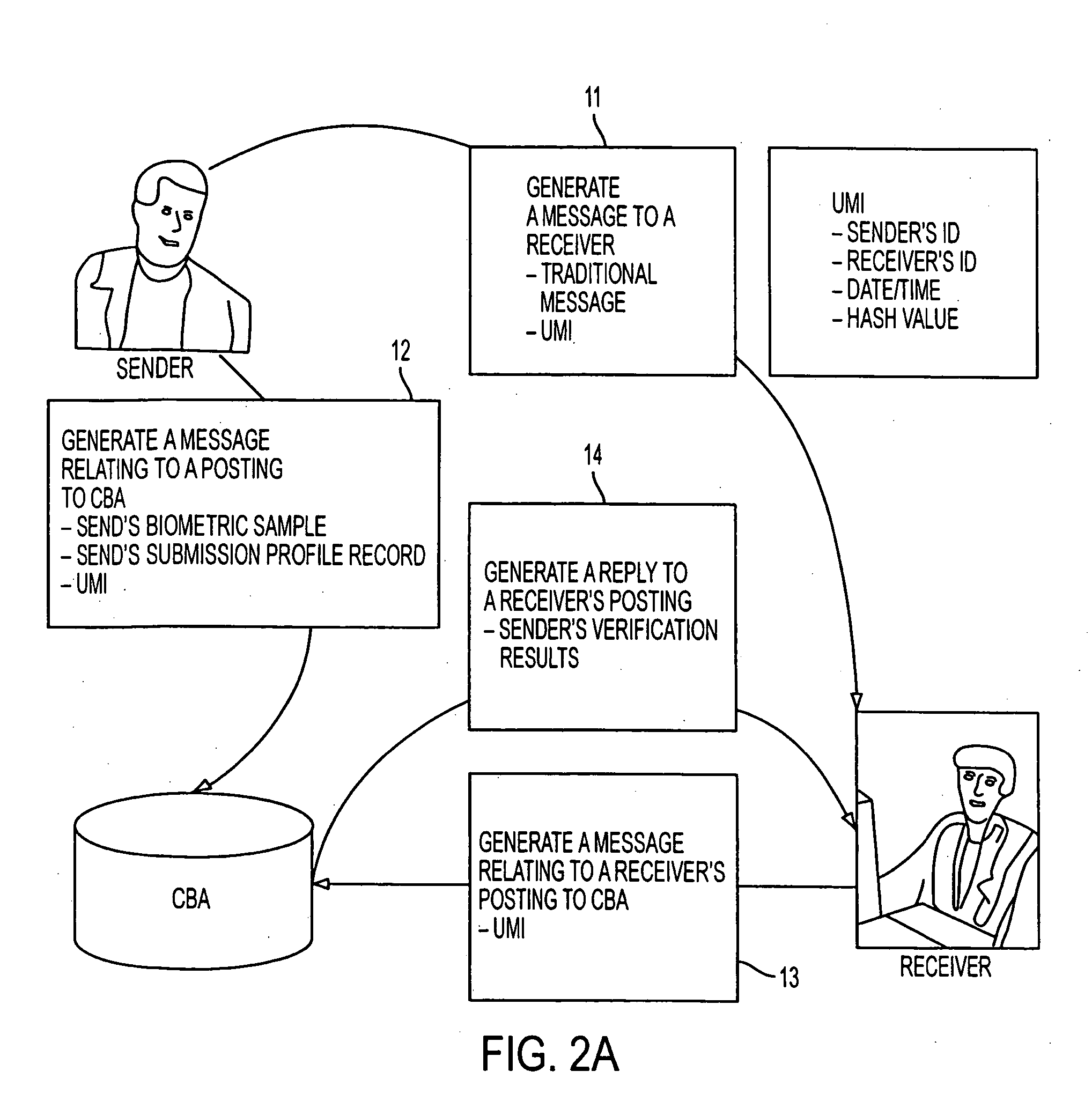
[0041] Specifically, in the present invention, a method to verify the identity only of the sender of a message is described. A sample transaction is a customer sending a message to their bank to wire transfer money into their stockbroker's account.

[0042] With reference to FIG. 2A, at step 11, a sender generates a message to a receiver. The message includes the substantive message? and the UMI.

[0043] Meanwhile, at step 12, the sender generates a message relating to a posting to the CBA. This message includes the sender's biometrics sample, the UMI, and the sender's is submission profile record. At step 13, it is necessary to take place only if the receiver desires verification of the sender's identity. In many cases (low risk level involved with message communication, low chance of suspected fraud, junk e-mail, etc.) this verification may not be desired, and the CBA process may never be completed. In this case, the step 12 will remain “unclaimed”. An aging off to expiration scheme c...

second embodiment

[0044] With reference to FIG. 2B, the invention is provided, wherein a method to verify the identity of both the sender and the receiver of a message is described. A sample transaction is someone sending a secure message to an important client. To accomplish this, a synchronous or secret key is created for the transaction by the sender, and held from the receiver until they have been biometrically identified to the satisfaction of the sender.

[0045] Specifically, at step. 21, a sender generates a message to a receiver. The message includes the substantive message encrypted with a synchronous key and the UMI.

[0046] Meanwhile, at step 22, the sender generates a message relating to a posting to the CBA. This message includes the sender's biometrics sample, the UMI, the sender's submission profile record, the synchronous key used in step, and the verification requirements record. At step 23, the receiver generates a message relating to a receiver posting to the CBA including the UMI, as...

third embodiment

[0047] Referring now to FIG. 2C, the invention is given, wherein a method to verify the identity of a person presenting themselves to complete any face-to-face transaction (authorized transactor or AT). A sample transaction is a credit card transaction at point of sale, a cash withdrawal at an ATM or teller window, or someone picking up their car at the mechanics shop.

[0048] Specifically, at step 31, at a point of transaction (POT) the POT operator (e.g., cashier) issues a message relating to a POT posting to CBA. This message includes the authorized transactor (AT)'s claimed identity, the AT's biometric sample and the POT submission profile record. At step 32, the CBA compares the biometric sample from the step 31 to that registered on the AT and generates the reply to the POT posting. This message includes only the AT's verification score / rating.


PUM


Abstract

A method performs biometric verifications to authenticate the identification of users using a central biometric authority (CBA). This allows parties to an electronic transaction to be assured of each other's identity. Specifically, at the sender side, a first message to a receiver is generated, wherein the first message includes a message text and a unique message identifier (UMI). At the sender side, a second message concerning a posting to the CBA is also generated, wherein the second message includes the sender's biometric sample, the UMI, and the sender's submission profile record. At a receiver side, it is decided that if a receiver wishes to verify the sender's identity and if so, the first message is automatically verified. At the receiver side, a third message concerning a receiver's posting to the CBA is issued, the third message including only the UMI, as received from the sender side. Finally, at the CBA, a reply to the third message is provided, the reply including the sender's verification result.

Description

FIELD OF THE INVENTION [0001] The present invention relates to an identity verification system; and, more particularly, to a method for effectively establishing the identification of users by utilizing a central biometric authority (CBA). BACKGROUND OF THE INVENTION [0002] It is known that a public / private key infrastructure is (PKI) is an excellent mechanism to ensure that data remains confidential and unchanged during transit over insecure networks such as the Internet. The PKI is based on the premise that a user has two mathematically related numerical keys, a private key and a public key, which serve to encrypt data. It is possible to secure a message by encrypting it with a sender's private key and a receiver's public key, which is obtained from a repository known as a certificate authority (CA). The receiver can read the message by decrypting it using his private key and the sender's public key. [0003] The keys used in the PKI are very long; and, the longer they are, the more ...

Claims


Application Information

Patent Timeline
IPC IPC(8): G06F21/00H04L9/00H04L9/32
CPCG06F21/32H04L9/006H04L2209/56H04L9/321H04L9/3231H04L9/0825
Inventor NANAVATI, SAMIR H.NANAVATI, RAJKUMAR
Owner FUSIONARC
Why Eureka
Try Eureka