Light wavelength converting apparatus, control method of the same, and image projecting apparatus using the same

a technology of light wavelength converting apparatus and control method, which is applied in the direction of instruments, semiconductor lasers, optical elements, etc., can solve the problems of large conversion efficiency of wavelength range, difficult to estimate control parameters with high precision, and power consumption is likely to increase in the apparatus of fig, so as to reduce consumption power

Inactive Publication Date: 2005-11-17
CANON KK
View PDF4 Cites 43 Cited by
  • Summary
  • Abstract
  • Description
  • Claims
  • Application Information

AI Technical Summary

Benefits of technology

[0012] The control portion includes a control parameter determiner, and a wavelength controller. The control parameter determiner is adapted to change a DBR current supplied to the DBR region and a phase current supplied to the phase region to obtain a changing point that corresponds to a discontinuous change in an electrical signal from the first optical detector, and to determine a control parameter for controlling the DBR current and the phase current such that the relationship between the DBR current and the phase current is not located in the changing point. The wavelength controller is adapted to control the DBR current and the phase current pursuant to the control parameter, such that an oscillation wavelength of the semiconductor laser can be continuously controlled.
[0014] The control method includes a step of changing a DBR current supplied to the DBR region and a phase current supplied to the phase region to obtain a changing point that corresponds to a discontinuous change in an electrical signal from the first optical detector, a step of determining a control parameter for controlling the DBR current and the phase current such that the relationship between the DBR current and the phase current is not located in the changing point, and a wavelength control step of controlling the DBR current and the phase current pursuant to the control parameter, such that an oscillation wavelength of the semiconductor laser can be continuously controlled.
[0017] According to the present invention, it is possible to achieve a light wavelength converting apparatus which does not necessarily require temperature stabilizing mechanism, such as a Peltier device, and is capable of being driven by reduced consumption power.

Problems solved by technology

With the SHG device 2, a wavelength range having a large conversion efficiency is limited.
It is hence difficult to estimate the control parameter with high precision.
However, the apparatus of FIG. 8 does not consider such a situation.
Power consumption is therefore likely to increase in the apparatus of FIG. 8.

Method used


Image

  • Light wavelength converting apparatus, control method of the same, and image projecting apparatus using the same
  • Light wavelength converting apparatus, control method of the same, and image projecting apparatus using the same
  • Light wavelength converting apparatus, control method of the same, and image projecting apparatus using the same

Examples


first embodiment

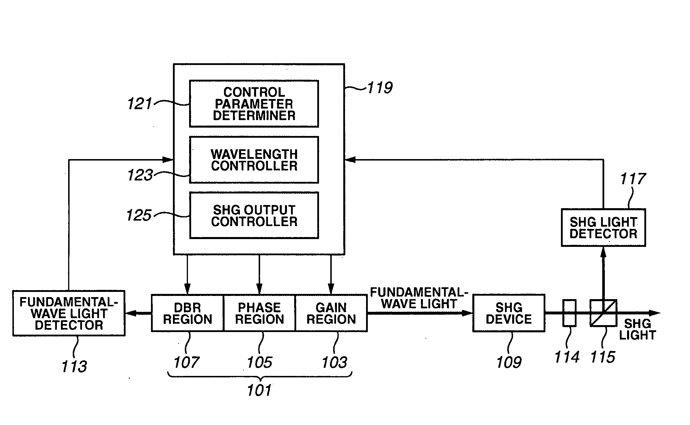
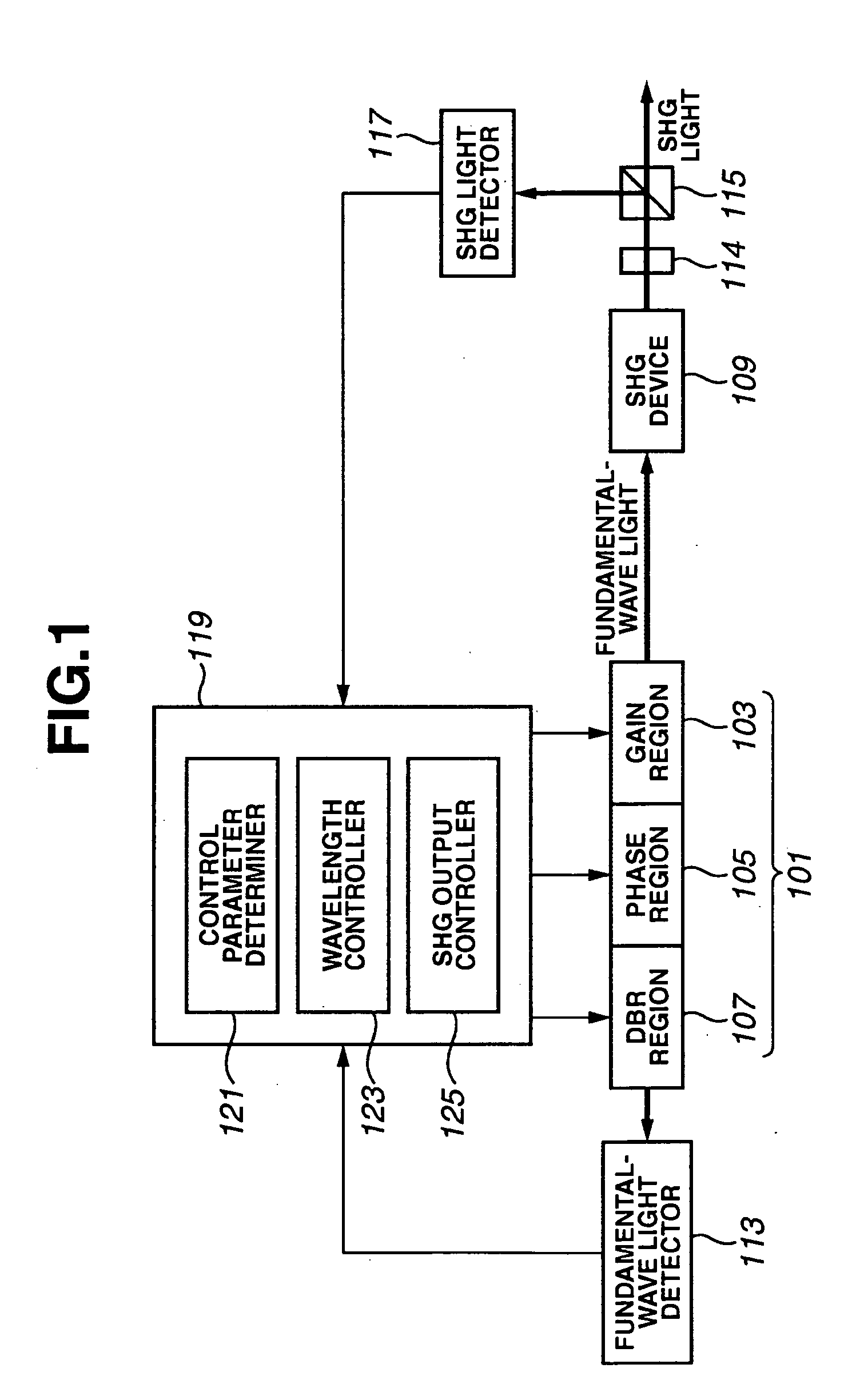
[0028]FIG. 1 illustrates the structure of a light wavelength converting apparatus according to the present invention. As illustrated in FIG. 1, a DBR semiconductor laser 101 includes a gain region 103, a phase region 105, and a DBR region 107 provided with a diffraction grating. The DBR semiconductor laser 101 emits fundamental-wave light. Temperatures of the phase region 105 and the DBR region 107 are controlled by injecting current perpendicularly to a pn junction provided therein, or injecting current into a thin-film heater provided therein. The refractive index of a waveguide is changed by such a change in the temperature. Phase and reflectivity for the fundamental-wave light in the DBR semiconductor laser 101 are accordingly adjusted to vary oscillation wavelength.

[0029] Fundamental-wave light emitted from a rear side of the semiconductor laser 101 is input into a fundamental-wave light detector 113. The fundamental-wave light detector 113 converts power of the fundamental-wav...

third embodiment

[0060] A description will now be given for a light wavelength converting apparatus with reference to FIG. 5. FIG. 5 illustrates the structure of a light wavelength converting apparatus of the third embodiment. In FIG. 5, the same portions or elements as those in FIG. 1 are designated by the same reference numerals.

[0061] The third embodiment is different from the first embodiment in that a temperature sensor 403 for supplying temperature information to the control portion 119 is provided on a sub-mount 401 on which the DBR semiconductor laser 101 is mounted, and in that the wavelength controller 123 stores a correcting coefficient for the temperature information from the temperature sensor 403. As for the other points, the third embodiment is the same as the first embodiment.

[0062] In the first embodiment, the wavelength continuous varying curve is represented by

a·IDBR2+b·Iphase2=(c(i)+c(i+1)) / 2

In this formula, the proportional coefficients a and b were determined to remain almo...

second embodiment

[0072] The determination of the wavelength continuous varying curve is not limited to the above-discussed description. It can also be carried out by fitting to an appropriate function from discretely-detected changing points, or by connecting changing points with straight lines to create a zigzag locus of changing points. It is naturally allowable to obtain the wavelength continuous varying curve considering the hysteresis as in the second embodiment, instead of acquiring the central line between the two adjacent loci of changing points.


PUM

PropertyMeasurementUnit
wavelengthaaaaaaaaaa
lengthaaaaaaaaaa

Abstract

A light wavelength converting apparatus includes a semiconductor laser having a gain region, a phase region, and a distributed Bragg reflection (DBR) region, a nonlinear optical device for receiving fundamental-wave light emitted from the semiconductor laser and outputting second harmonic wave light, a first optical detector for monitoring an output of the fundamental-wave light, a second optical detector for monitoring the second harmonic wave light, and a control portion for controlling at least a drive current for driving the semiconductor laser. The control portion includes a control parameter determiner, and a wavelength controller. The control parameter determiner changes a DBR current supplied to the DBR region and a phase current supplied to the phase region to obtain a changing point that corresponds to a discontinuous change in an electrical signal from the first optical detector, and determines a control parameter for controlling the DBR current and the phase current such that the relationship between the DBR current and the phase current is not located on the changing point. The wavelength controller controls the DBR current and the phase current pursuant to the control parameter such that an oscillation wavelength of the semiconductor laser can be continuously controlled.

Description

BACKGROUND OF THE INVENTION [0001] 1. Field of the Invention [0002] The present invention relates to a light wavelength converting apparatus for converting light of a semiconductor laser or a laser diode (LD) into second harmonic wave light, and particularly relates to a light wavelength converting apparatus for emitting laser light, which is capable of high-speed modulation driving, and can be used as a light source for laser display, optical recording, optical measurement, etc. [0003] 2. Description of the Related Background Art [0004] A variety of attempts for conversion of LD light into light at another wavelength have been made using a nonlinear optical material. According to such technology, it becomes possible to generate laser light in a wavelength range, such as a green range or an ultraviolet range, that is not yet put into practice with the LD. Such a light source can be expected to be usable as a light source for laser display or optical recording. Particularly, research...

Claims


Application Information

Patent Timeline
Patent Type & Authority Applications(United States)
IPC IPC(8): G02F1/377G02B26/10H01S3/10H01S5/00H01S5/02H01S5/06H01S5/0625H01S5/0687H01S5/125
CPCH01S5/005H01S5/0092H01S5/06804H01S5/0617H01S5/06256H01S5/02248H01S5/02325
Inventor FURUKAWA, YUKIOSAKATA, HAJIMEFUJII, KAZUNARI
Owner CANON KK
Why Eureka
Try Eureka