Turbocharger control system and propeller control system by a motor

a technology of propeller control and turbocharger, which is applied in the direction of propellers, vehicles, water-acting propulsive elements, etc., can solve the problems of increasing engine load, reducing engine load, and pilots having to control both throttle control levers and speed control levers simultaneously, and achieves cost-effective effect. simple

Inactive Publication Date: 2005-11-17
BRP ROTAX
View PDF20 Cites 14 Cited by
  • Summary
  • Abstract
  • Description
  • Claims
  • Application Information

AI Technical Summary

Benefits of technology

[0009] It is, therefore, an object of the present invention to provide a simple, cost-effective propeller governor having improved characteristics.
[0010] It is another object of the invention to provide a simple, cost-effective turbocharger system having improved characteristics.
[0011] It is yet another object of the invention to provide an aircraft control system through which the operation of an aircraft can be greatly simplified.
[0012] It is yet another object of the invention to provide an aircraft control system through which the safe operation of an aircraft can be enhanced.

Problems solved by technology

As the pitch increases, the load on the engine increases.
Conversely, as the pitch decreases, the load on the engine decreases.
A disadvantage of this system is that the pilot must control both the throttle control lever and the speed control lever simultaneously.
Obviously, the pilot may select less than optimum speed control settings for a given throttle setting.
Excess wear and tear on the engine and poor fuel efficiency may result from these less than optimal settings.
Although this method is effective for controlling automotive applications, it is extremely problematic for applications used on aircraft engines.
This may result in the waste gate being either fully opened or fully closed.
This, in turn, may result in an abrupt drop in charge pressure that may result in a loss of power.
Alternatively, this may result in an increase in charge pressure, with a corresponding risk of damage to the engine.
Both situations are hazardous in aircraft engine applications.
In principle, excess pressure can be dissipated through special “pop-off”, or alternatively, relief valves, although such valves are relatively costly.
However, the system is relatively costly.
The relatively high weight of the system is also a disadvantage.
In addition, there is no redundancy built into the system, i.e., there is no backup system that can perform system functions that may be lost in the event of a failure.
However, in the event of a system failure in a hydraulic-mechanical system, it cannot be excluded that under unfavourable conditions, charge pressure could tend towards an extreme value, and this eventuality is associated with the dangers discussed heretofore.

Method used


Image

  • Turbocharger control system and propeller control system by a motor
  • Turbocharger control system and propeller control system by a motor
  • Turbocharger control system and propeller control system by a motor

Examples


Embodiment Construction

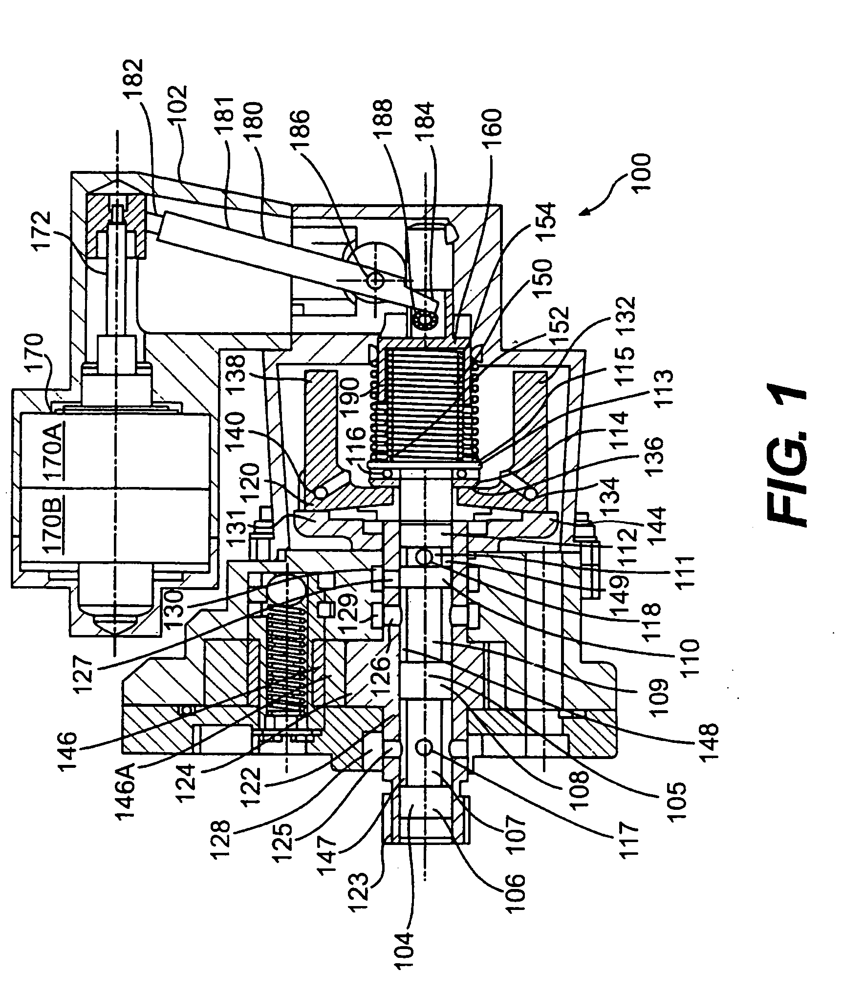
[0030]FIG. 1 shows a preferred embodiment of the propeller governor 100 of the present invention. The propeller governor 100 includes a housing 102 within which a plunger valve 104 is moveably disposed. The plunger valve 104 is a hydraulic control valve through which the governor controls the oil pressure at a propeller pitch controller (not shown). The plunger valve 104 may also be referred to as a pilot valve. Unlike most of the features of the governor 100 illustrated in FIG. 1, the plunger valve 104 is almost entirely not shown in cross-section. The plunger valve includes an- elongate body 105 that includes a plurality of generally cylindrical sections 106-112 connected to each other into a unitary body. A first section 106 includes a large diameter. A second section 107 includes a small diameter. A third section 108 includes a large diameter. A fourth section 109 includes a small diameter. A fifth section 110 includes a large diameter. A sixth section 111 includes a small diame...


PUM


Abstract

An aircraft control system includes a propeller governor in which a motor is used to apply a compression force on a speeder spring, and a turbocharger in which a motor is used to actuate a needle valve associated with a diaphragm cell. An electronic control unit may be used to control the motor in the propeller governor and the motor in the turbocharger. The integration of the propeller governor and the turbocharger into a single control system decreases the number of individual adjustments that must be performed manually by the pilot.

Description

CROSS-REFERENCE TO RELATED APPLICATIONS [0001] This is a continuation of U.S. patent application Ser. No. 10 / 636,627 filed Aug. 8, 2003, which is a divisional of U.S. patent application Ser. No. 09 / 933,117, which was filed on Mar. 16, 2002 and which claimed priority to U.S. Provisional Patent Application No. 60 / 226,579, which was filed on Aug. 21, 2000. As a result, this application indirectly claims priority to the same provisional patent application. The disclosures of the provisional and non-provisional patent and divisional applications are incorporated herein by reference.FIELD OF THE INVENTION [0002] The present invention relates to a method and apparatus for controlling the turbo charging of an internal combustion engine, in particular an aircraft engine, as well as a method and apparatus for controlling an aircraft propeller. BACKGROUND OF THE INVENTION [0003] Aircraft are controlled by a throttle control lever, which adjusts a throttle valve in the aircraft engine, and a sp...

Claims


Application Information

Patent Timeline
Patent Type & Authority Applications(United States)
IPC IPC(8): F02B37/18F02D9/02F02D29/02F02M35/16F03D1/00
CPCF02B37/18F02D9/02Y02T10/144F02M35/10157F02M35/16F02D29/02Y02T10/12
Inventor KOCH, THOMASLIPPITSCH, HEINZBAYERL, JOHANNMOSENEDER, MANFREDMAYR, GERALD
Owner BRP ROTAX
Why Eureka
Try Eureka