Drum, in particular a drum forming a turbomachine rotor, a compressor, and a turboshaft engine including such a drum

a technology of turbomachine rotor and compressor, which is applied in the direction of rotors, machines/engines, climate sustainability, etc., can solve the problems of large cost of raw materials and subsequent machining, material loss during machining, and long and expensive welding operations, so as to improve the effect of stressing

Active Publication Date: 2005-11-17
SN DETUDE & DE CONSTR DE MOTEURS DAVIATION S N E C M A
View PDF7 Cites 18 Cited by
  • Summary
  • Abstract
  • Description
  • Claims
  • Application Information

AI Technical Summary

Benefits of technology

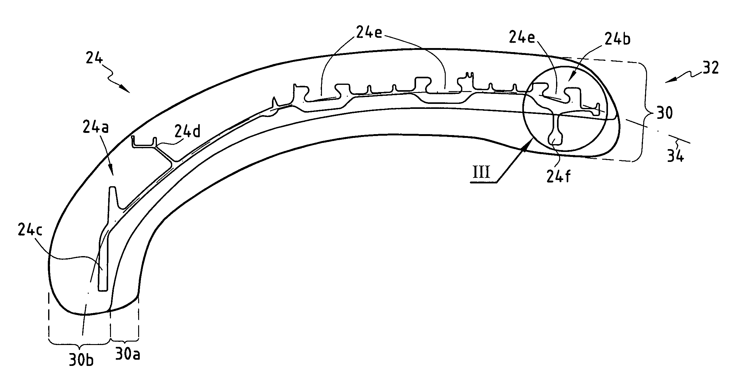
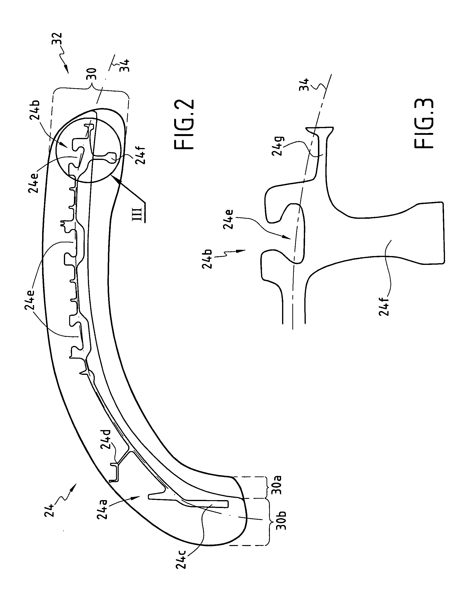
[0018] In a first embodiment of the drum of the present invention, said downstream end defines an annular housing coaxial about said longitudinal axis, said housing being radially open towards the outside, and said composite assembly is annular and wound around said downstream end, being positioned in said housing. This solution makes it possible to obtain a single stiffener that provides the drum with overall reinforcement against forces, in particular centrifugal forces directed radially outwards, and tending to deform the drum.
[0019] In a second embodiment of the drum of the present invention, said downstream end forms a series of axial protrusions, and said sti...

Problems solved by technology

Obtaining such a forging therefore requires a large quantity of raw material to be used, giving rise to large costs in terms of raw materials and subsequent machining, with material being lost durin...

Method used


Image

  • Drum, in particular a drum forming a turbomachine rotor, a compressor, and a turboshaft engine including such a drum
  • Drum, in particular a drum forming a turbomachine rotor, a compressor, and a turboshaft engine including such a drum
  • Drum, in particular a drum forming a turbomachine rotor, a compressor, and a turboshaft engine including such a drum

Examples


first embodiment

[0053] In a first embodiment shown in FIGS. 4A and 4B, the annular axial protrusion 24g forming the portion of the drum that is situated furthest downstream defines a circular annular housing 124h around the longitudinal axis 12, this housing 124h being open in a radially outward direction, i.e. facing away from the longitudinal axis 12, so as to be capable of receiving the composite assembly 140.

[0054] In a first variant shown in FIG. 4A, the annular housing 124h extends on both sides of the generatrix line 134.

[0055] In a second variant shown in FIG. 4B, the housing 124h is offset outwards from the generatrix line 134: in this way, the wound composite assembly 140 constituting the stiffener is off-centered relative to the generatrix line 134. This preferred solution serves to improve the mechanical strength performance of the drum that presents such an arrangement.

second embodiment

[0056] In a second embodiment shown in FIGS. 5A and 5B, the furthest downstream portion of the downstream end 124b presents multiple axial protrusions 124i which are regularly spaced apart radially along the longitudinal axis 12.

[0057] Each of these axial protrusions 124i is designed to receive a wound composite assembly 140 which is wound in the form of a sleeve around said protrusion 124i.

[0058] The sleeve formed by the wound composite assembly 140 may have an opening at each of its ends, or in preferred manner, as shown in FIGS. 5A and 5B, it may present a U-shape longitudinal section engaged around the axial protrusion 124i.

[0059] The sleeve may be circularly cylindrical about the axis 136 that is parallel to the longitudinal axis 12, or it may present a cross-section that is elongate, e.g. being oval, oblong, or the like.

[0060] In a first variant of the second embodiment, as shown in FIG. 5A, the axial protrusions 124i together with the wound composite assemblies 140 are cen...


PUM

PropertyMeasurementUnit
Thermosettingaaaaaaaaaa

Abstract

The drum of the invention is generally in the form of a body of revolution about a longitudinal axis, being made of a metal alloy and extending between an upstream end and a downstream end along a curved profile capable of being circumscribed in an annular envelope extending around said longitudinal axis, said profile extending radially about a surface of revolution presenting a generatrix line, said downstream end being provided with a stiffener. In characteristic manner, said stiffener is provided with at least one composite assembly mounted on said downstream end, said composite assembly comprising fibers and a polymer matrix. The drum is preferably for use in constituting a rotor of a low pressure compressor.

Description

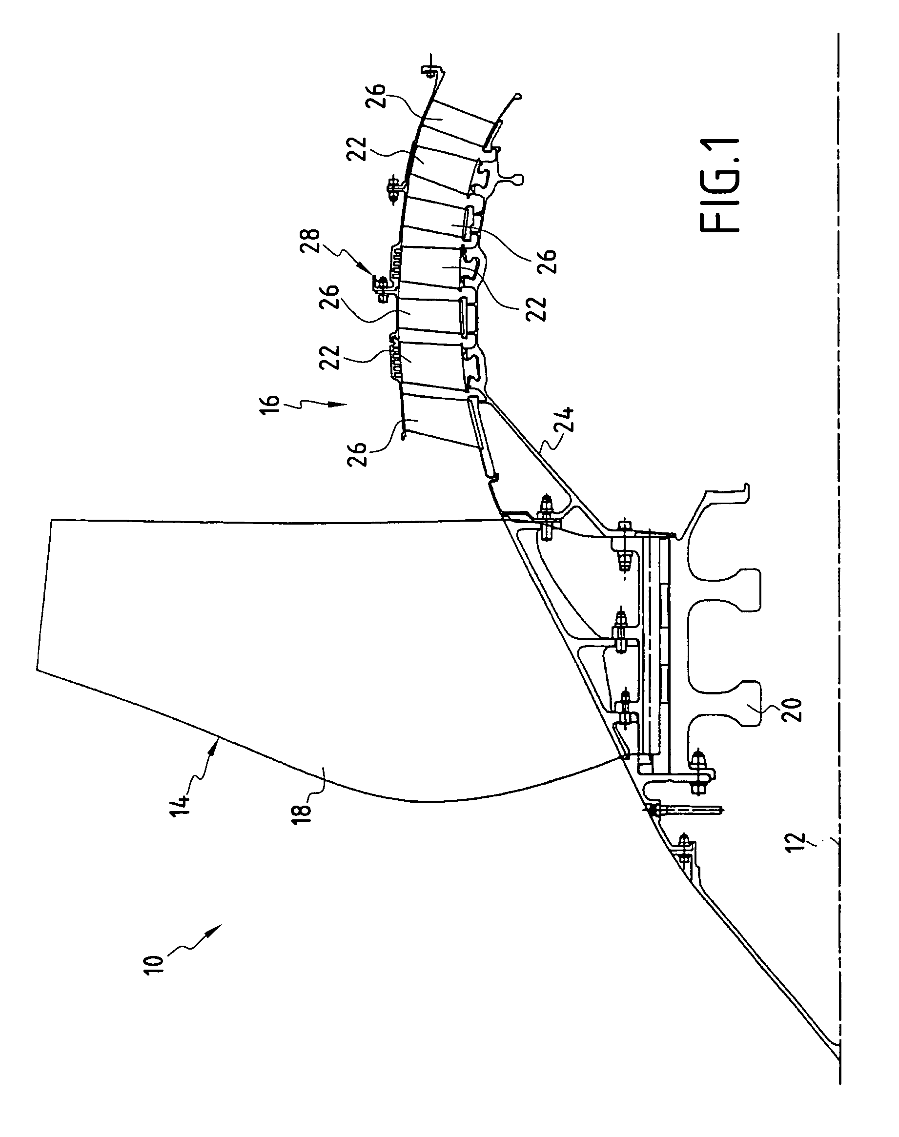
[0001] The invention relates to a turbomachine rotor, in particular for aviation purposes. [0002] More particularly, the present invention relates to making a single-block drum for a turbomachine rotor, in particular for an axial type compressor, specifically a low pressure compressor. The adjective “single-block” is used to mean a drum made as a single piece or as a plurality of parts bonded together in rigid manner. BACKGROUND OF THE INVENTION [0003] Compressors of this type, which are used in particular in turbojet engines, are constituted by a rotor which instead of comprising a succession of separate disks stacked one after another, comprises a single drum for receiving the series of blades of different stages. [0004] Conventionally, the single drum has recesses or retention grooves machined therein, in a disposition that leaves gaps between adjacent stages for receiving the blades of the stator stages that are secured to a fixed portion presenting a casing. [0005] The blades a...

Claims


Application Information

Patent Timeline
IPC IPC(8): F01D5/06F02C7/00F01D5/28F01D5/30F01D7/00F04D29/32
CPCF01D5/06F01D5/282F01D5/3038F04D29/322Y02T50/672F05D2220/327F05D2300/224F05D2300/603F05D2300/614F05D2220/325F05D2300/702Y02T50/60
Inventor MONS, CLAUDE
Owner SN DETUDE & DE CONSTR DE MOTEURS DAVIATION S N E C M A
Why Eureka
Try Eureka