Laser cooling system and method

a cooling system and laser technology, applied in the field of lasers, can solve the problems of significant turbulence, increased cost, and more difficult work

Inactive Publication Date: 2005-11-24
VIDEOJET TECH INC
View PDF40 Cites 18 Cited by
  • Summary
  • Abstract
  • Description
  • Claims
  • Application Information

AI Technical Summary

Benefits of technology

[0016] A further significant advantage of using a folded sheet is that the folded sheet can be provided so that it is extensible and compressible by its interconnecting portions. The folded sheet can then be extended or compressed by a desired amount before bonding it to the cooling face in its extended or compressed state. This allows adjustment of the fin spacing, and the distance of maximum extent of the fins from the cooling face. This kind of freedom is not possible with a conventional fin array where the fin size and pitch is fixed at the time of manufacture

Problems solved by technology

Second, the fins formed by the interconnecting portions of the sheet can present a high-drag to a fluid flow being forced past the fins by a fan or pump, thereby inducing significant tu

Method used


Image

  • Laser cooling system and method
  • Laser cooling system and method
  • Laser cooling system and method

Examples


Embodiment Construction

[0023] The following description of exemplary embodiment(s) is merely illustrative in nature and is in no way intended to limit the invention, its application, or uses.

[0024] Although the discussion herein may not discuss all details associated with the cooling of laser systems, such details, as known by one of ordinary skill, are intended to be included within the scope of embodiments discussed herein.

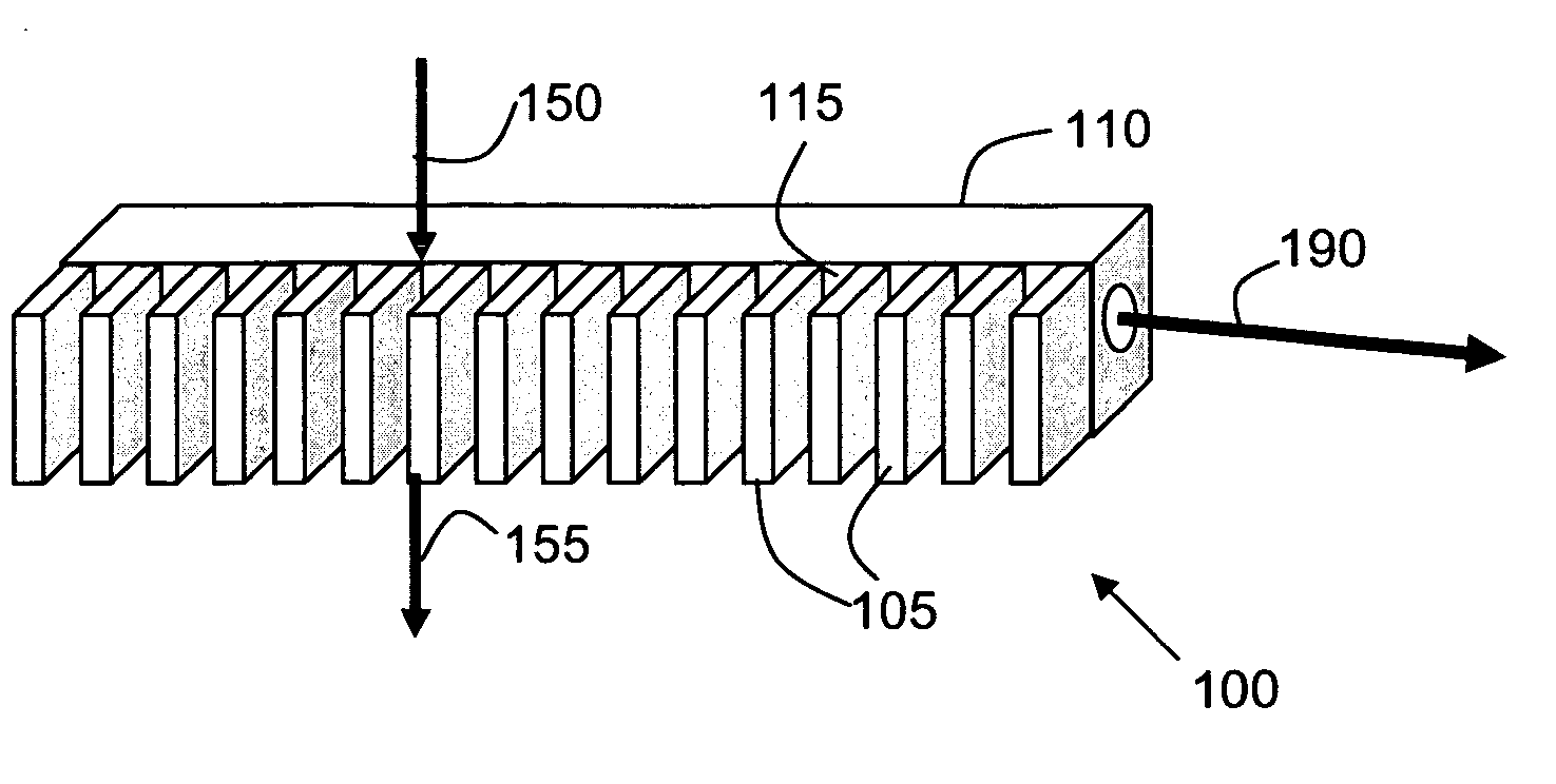
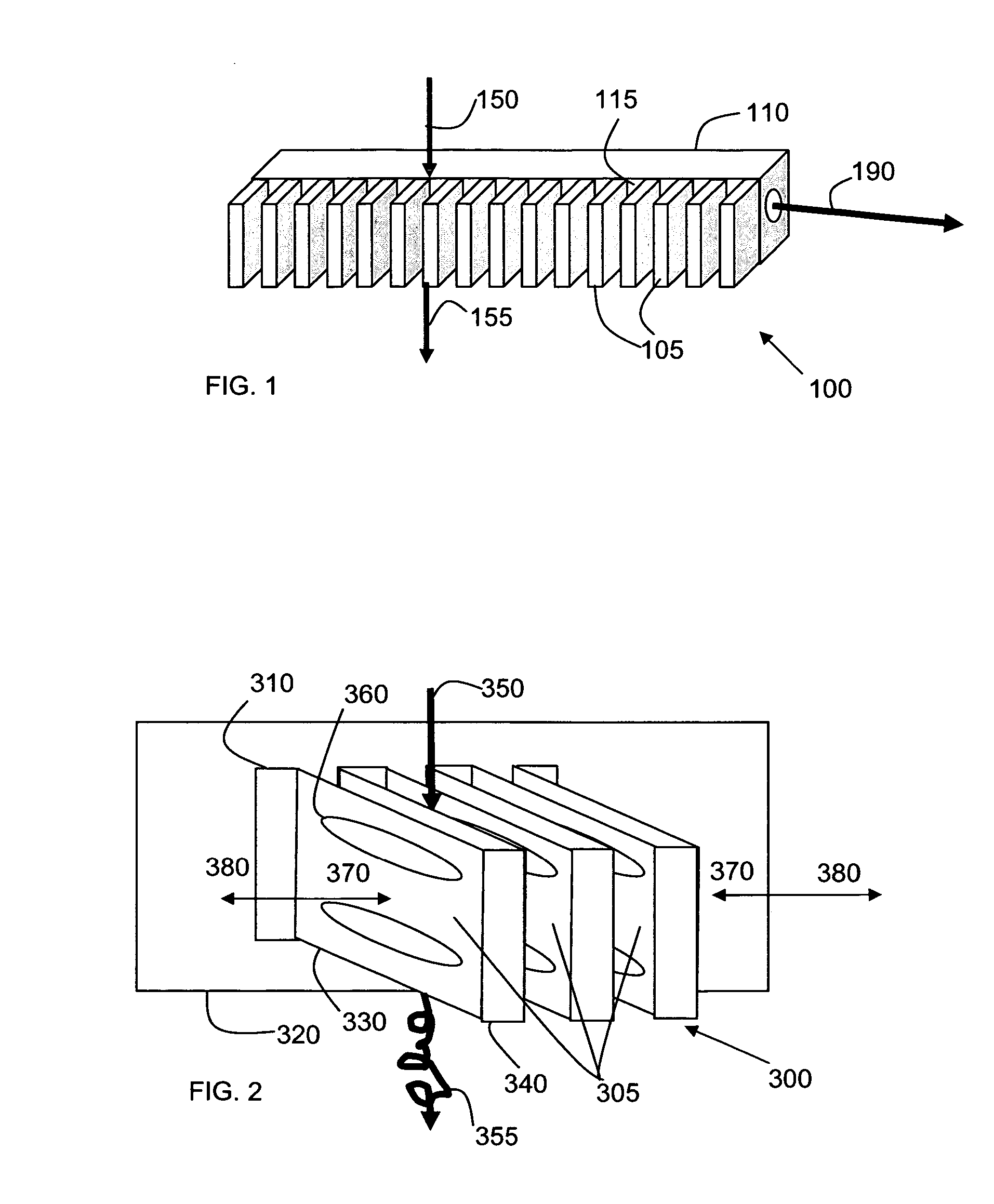
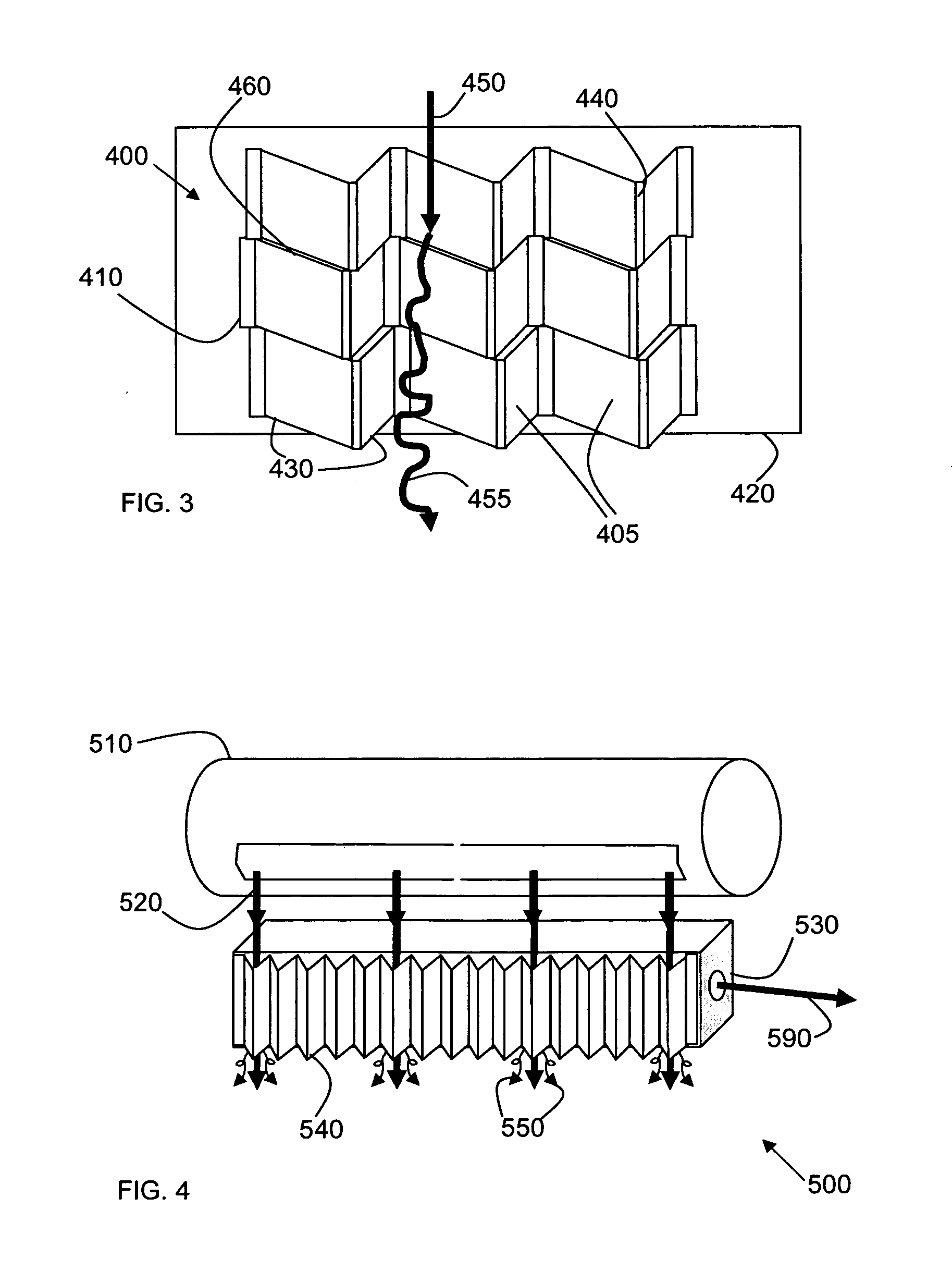
[0025] Fluid cooling of a laser system (e.g. air, gas, water, and other fluids as can be used as determined by one of ordinary skill), can involved flowing the fluid over a fin array, where the fin array conducts heat from the laser. The heated fin array in turn heats the flowing fluid, which convects the heat away from the fin array. The heated portion of the fluid flow depends upon the area of the fin array, the thermal transfer efficiency between the fins and the cooling fluid, and the volume of the fluid passing over the fin array. Laminar fluid flow has a lower heat transfer co...


PUM


Abstract

A folded sheet is used as a basis for a fin array to cool laser modules. The folded sheet has flat portions that are connected in thermal contact with the laser module, and fins formed by interconnecting portions. This arrangement is highly convenient for assembly, inexpensive, and provides for highly effective heat exchange.

Description

FIELD OF THE INVENTION [0001] The present invention relates to lasers, more particularly to providing lasers with suitable cooling fins. BACKGROUND OF THE INVENTION [0002] Typical cooling of a laser utilizes cooling fin arrays coupled with fans to convect heat away from the laser. The fins are typically milled into the body of the laser housing or are part of an extruded heat sink that is bolted to the laser body. In either case the milling or extruding limits the size, pitch and shape of the resulting fins. In particular, heat transfer is largely dependent on the heat transfer surface area. When milling fins, the pitch of the fins, i.e. the number of fins per unit distance, is limited by the milling tool size. The extrusion process has limits on fin width, fin pitch and the fin width to length ratio. [0003]FIG. 1 illustrates a conventional laser package 100, having a laser module 110 with an associated laser beam 190 also being illustrated. The laser module 110 has a cooling face 1...

Claims


Application Information

Patent Timeline
IPC IPC(8): F28F3/02F28F7/00H01S3/04
CPCF28F3/025H01S3/0407H01S3/0405H01S3/0404
Inventor MONTY, NATHAN P.LIND, KENNETH A.ARMBRUSTER, KEVIN L.
Owner VIDEOJET TECH INC
Why Eureka
Try Eureka