Mass spectrometer

Active Publication Date: 2005-11-24
HITACHI HIGH-TECH CORP
View PDF7 Cites 36 Cited by
  • Summary
  • Abstract
  • Description
  • Claims
  • Application Information

AI Technical Summary

Benefits of technology

[0034] The mass spectrometer according to the invention is to be described briefly. After controlling the energy of electrons generated by the electron source to 1 eV or lower, the electrons are twined around the static magnetic fields and electrons are introduced into the linear RF quadrupole electric fields formed by linear RF generating multipole electrodes and negative chemical ionization is conducted within the linear converging potential of the linear RF quadrupole electric fields. The created negative ions of the sample are converged through a lens or the like and introduced at a high efficiency to the mass spectrometric section. As a result, a mass spectrometer having a negative chemical ion source section of a high efficiency and capable of detecting negative ions

Problems solved by technology

Owing to this, it involves a problem that no high sensitivity can be obtained in the method of using the negative chemical ionization as compared with the method of using the positive chemical ionization as pointed out so far.
Even when the low energy electrons are intended to be introduced to the inside of the ion trap by the same method as in the case of conducting the positive chemical ionization, since the low en

Method used


Image

  • Mass spectrometer
  • Mass spectrometer
  • Mass spectrometer

Examples


Example

Embodiment 1

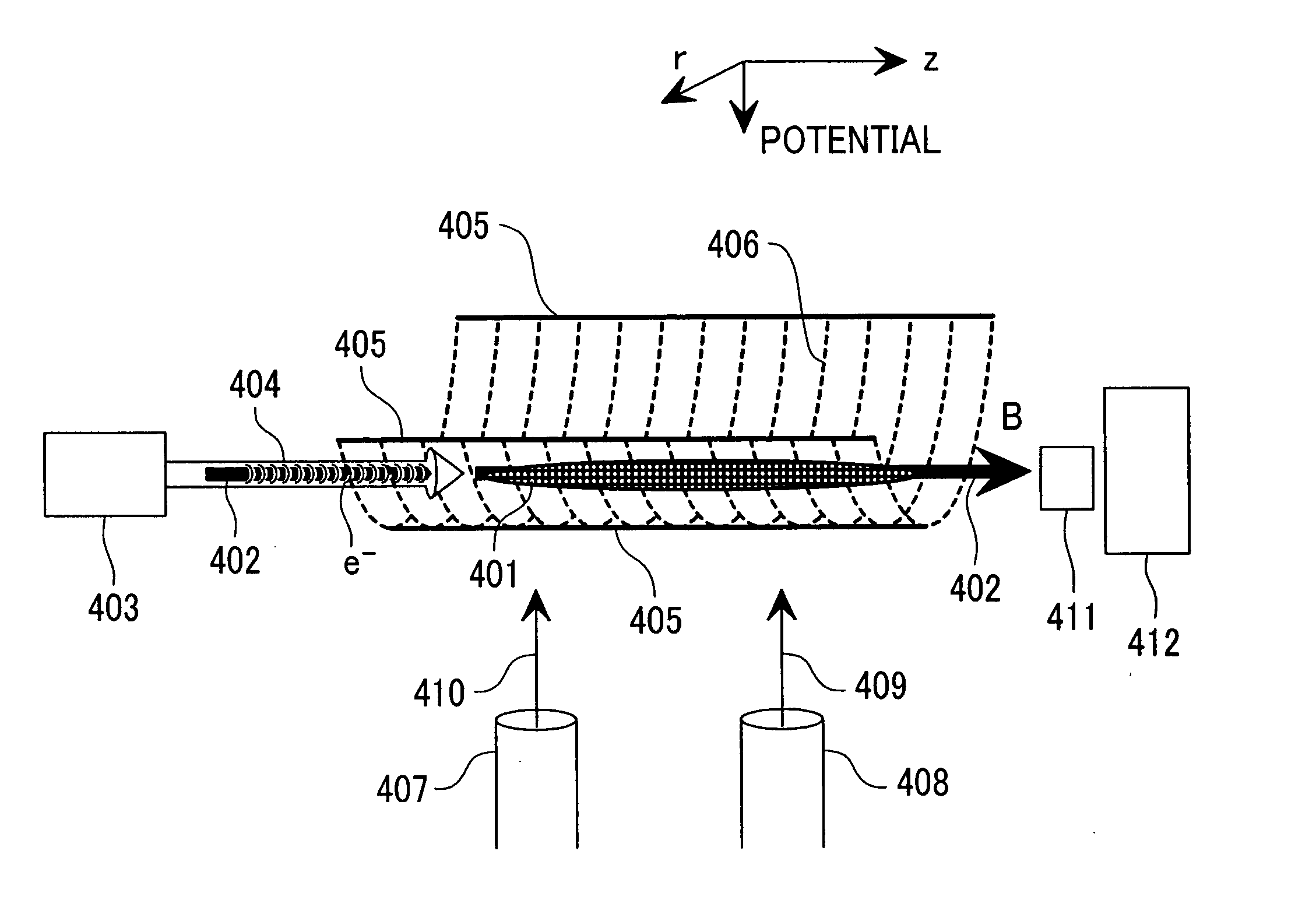
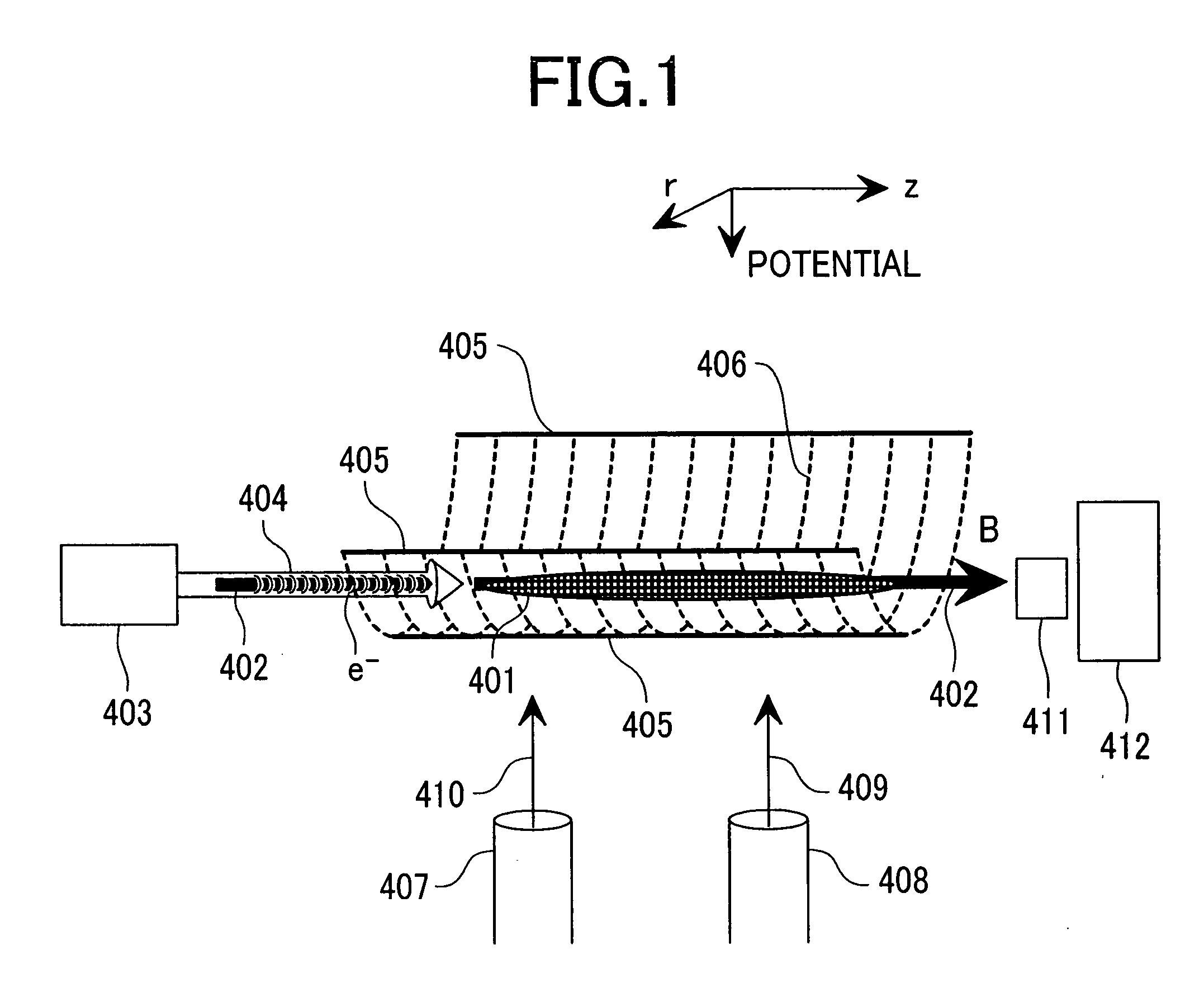
[0047]FIG. 1 is a view for explaining a main constitution of a mass spectrometer according to Embodiment 1 of the invention. Constitution and function of elements shown in FIG. 1 are to be described.

[0048] A linear ion trap potential 406 shown by plural broken lines is formed of linear RF multipole electric fields formed in the direction r perpendicular to the direction z. A static magnetic field 402 indicated by a solid arrow in the horizontal direction is superimposed in parallel or substantially in parallel on a center axis where the linear RF multipole electric fields are substantially at 0 and shown by a static magnetic field intensity B. In the direction along with the center axis of a linear converging potential 406 (direction z), a gradient (electric field gradient) for the DC potential 405 shown by a solid line is not formed.

[0049] A sample gas is introduced from a sample gas introduction pipe 408 as a portion of a sample gas introduction system is introduced...

Example

[0060] Embodiment 2 of the invention to be described later shows an example of a mass spectrometer using a three dimensional ion trap mass spectrometer. Since it is considered that the linear ion trap mass spectrometer based on mature techniques in recent years is effective for enhancing the sensitivity, an example of the mass spectrometer using the linear ion trap mass spectrometer is to be described in Embodiment 3 to be described later.

[0061] As shown in FIG. 1, since the DC potential 405 has no gradient (electric field gradient), it is highly plausible that 50% of the sample ions is introduced into the mass spectrometric section 412, while remaining 50% of them moves to the electron source 403 and lost in probabilistic point of view. That is, the utilization efficiency for the created sample ion is 50%.

[0062] Since Embodiment 2 of the invention to be described later has a constitution of not providing the electric field gradient in the direction of the center axis where the li...

Example

[0064] While Embodiment 2 of the invention to be described later is inferior to Embodiment 3 of the invention to be described later, since it has a simple constitution of apparatus, it is advantageous in view of a reduced cost.

(Explanation for the Constitution of Generating Static Magnetic Field)

[0065]FIG. 2, FIG. 3, FIG. 4, and FIG. 5 are, respectively, views for explaining first, second, third, and fourth examples of the constitution of the ion source section for creating positive or negative ions in Embodiment 1 and each of the embodiments of the invention. The ion source section comprises at least linear multipole electrodes for forming a linear RF multipole electric field in the direction r in perpendicular to the direction z, a magnet for generating a magnetic field in the direction z, a magnetic body constituting a magnetic circuit and an insulator for electric insulation.

[0066] Each of FIG. 2, FIG. 3, FIG. 4 and FIG. 5 is a cross sectional view including the center axis ...


PUM


Abstract

A mass spectrometer having an ion source section capable of creating positive ions and negative ions at high efficiency. The ion source is comprised of an ion source section for creating ions of a sample gas, a mass spectrometric section for conducting mass separation of created ions, linear RF generating multipole electrodes, magnetic fields generation means, a sample gas introduction system, a reaction gas introduction system and an electron source in which the linear RF generating multipole electrodes generate linear RF multipole electric fields. A static magnetic fields is applied in parallel on the center axis where the linear RF multipole electric fields are zero. A sample gas and a reagent gas are introduced into the ion source section. Electrons are injected for creating reaction of the positive ions or negative ions.

Description

CLAIM OF PRIORITY [0001] The present invention claims priority from Japanese application JP 2004-152835 filed on May 24, 2004, the content of which is hereby incorporated by reference to this application. BACKGROUND OF THE INVENTION [0002] The present invention concerns a mass spectrometry and, particularly, it relates to a mass spectrometer that can be utilized, for example, for the detection of contaminants such as residual agricultural chemicals present by slight amount in atmospheric air, drinking water, foods, etc. or detection of dangerous matters. [0003] Mass spectrometry is an essential technique as means for identifying substances and has been utilized generally for application uses such as detection of environmental food contaminants present by slight amount in atmospheric air, drinking water, foods, etc., or detection of dangerous matters. [0004] In mass spectrometry, molecular samples separated from specimen by using an appropriate pretreatment device such as a gas chrom...

Claims


Application Information

Patent Timeline
IPC IPC(8): G01N27/62H01J49/06H01J49/10H01J49/26H01J49/42
CPCH01J49/0095H01J49/145H01J49/063
Inventor BABA, TAKASHISATAKE, HIROYUKITAKADA, YASUAKI
Owner HITACHI HIGH-TECH CORP
Why Eureka
Try Eureka