
Electronic control unit, electric power-assisted steering device and transmission ratio-variable steering unit

a technology of electric power-assisted steering and control unit, which is applied in the direction of motor/generator/converter stopper, dynamo-electric converter control, instruments, etc., can solve the problems of abrupt decrease of steer-assist force, circuit to be broken down, and no voltage for driving to the switching elements of the inverter, etc., to reduce the unit price, suppress the cost of production, and prevent the effect of circuit or parts from being broken

Active Publication Date: 2005-11-24
DENSO CORP
View PDF45 Cites 21 Cited by
  • Summary
  • Abstract
  • Description
  • Claims
  • Application Information

AI Technical Summary

Benefits of technology

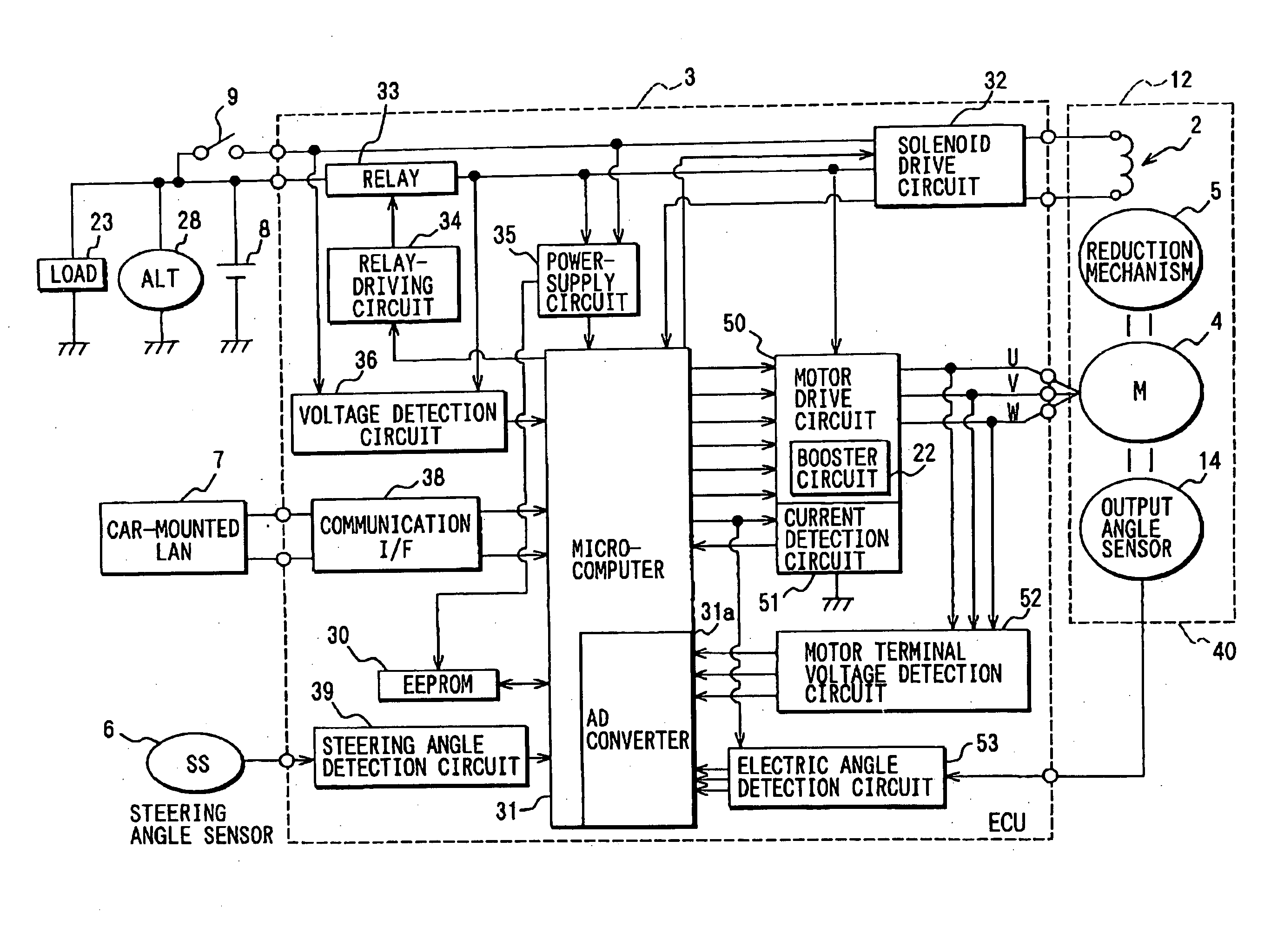
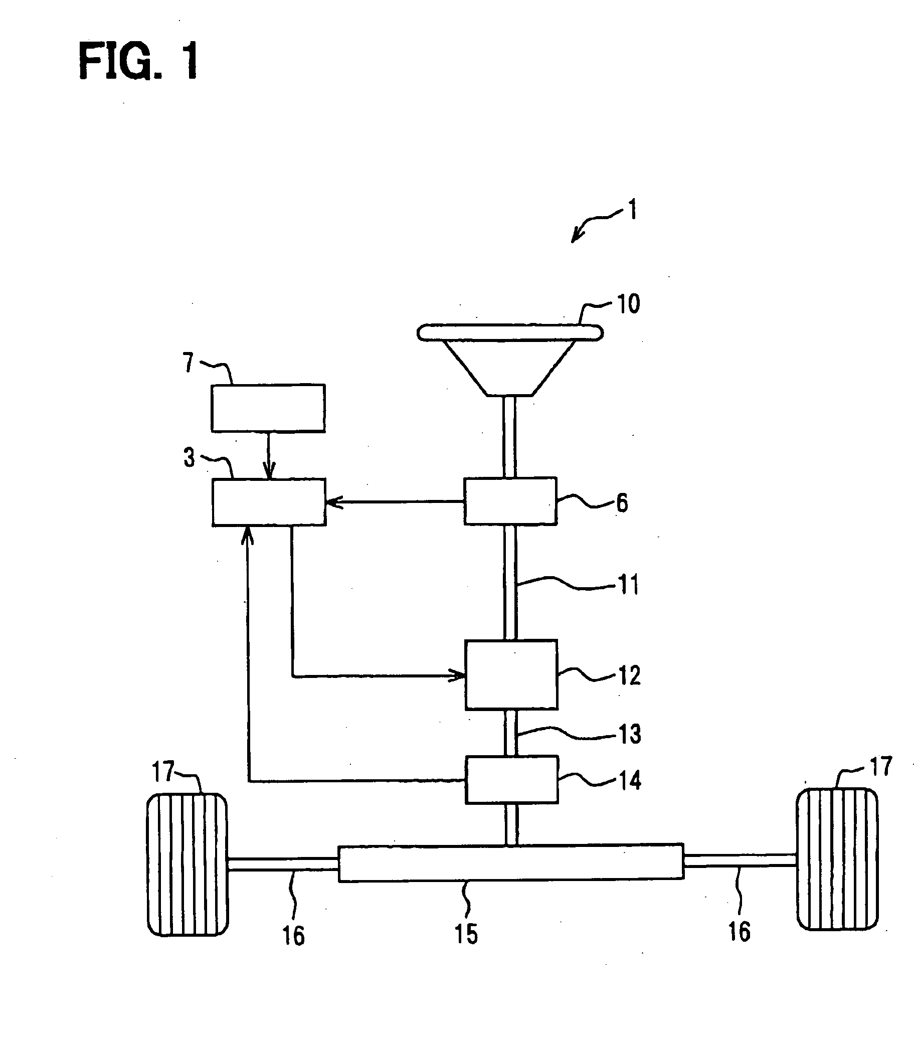
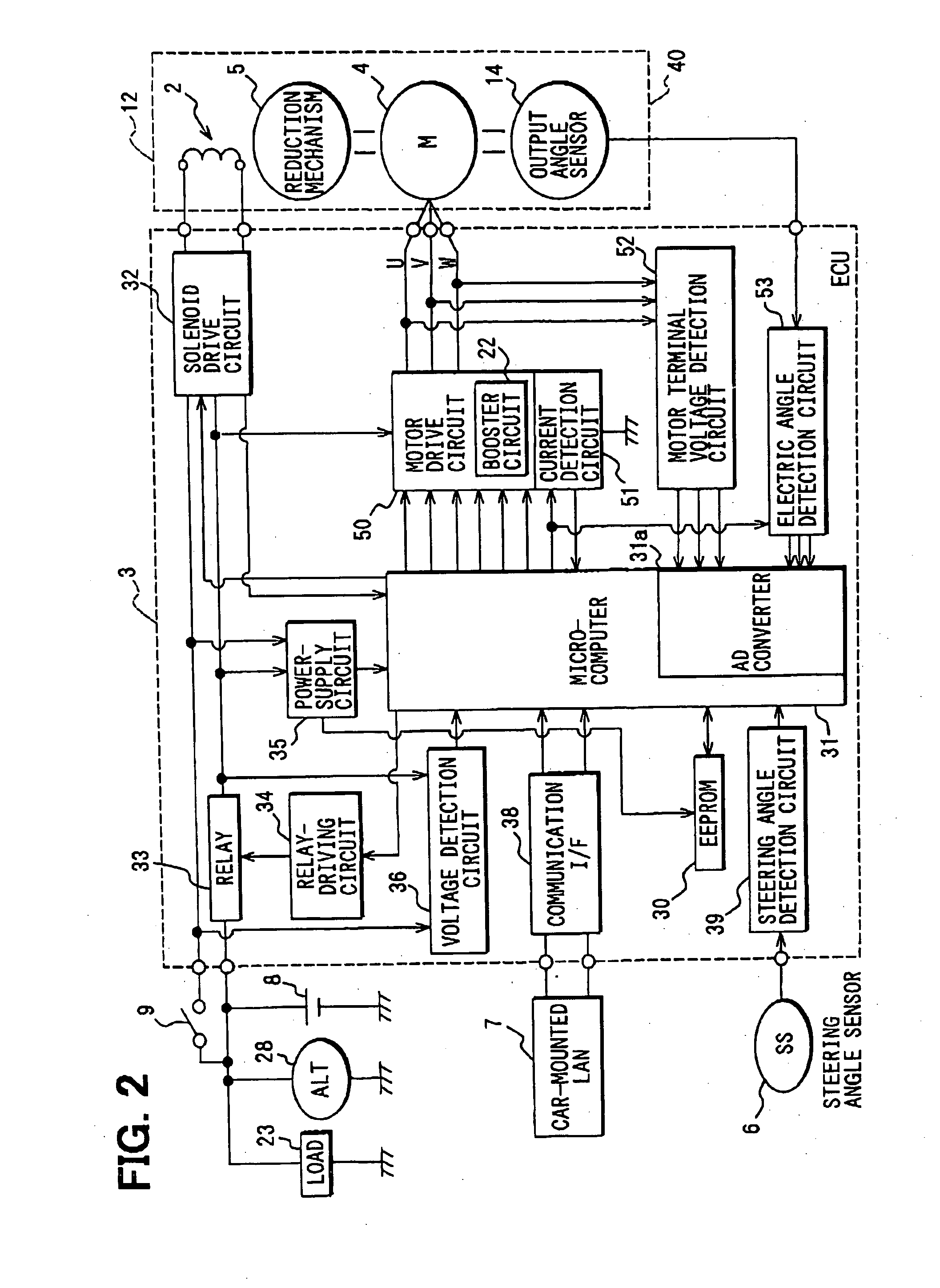
The present invention provides an electronic control unit, an electric power-assisted steering device, and a transmission ratio-variable steering unit that can produce a sufficient boosted voltage even when the supplied voltage becomes high. This is achieved by an inverter that drives the switching elements and booster means that boosts the DC voltage to a higher level and outputs it to the inverter. The boosted voltage is necessary for driving the switching elements and ensuring the motor operates without breaking down. The electronic control unit can be shared among multiple systems with different power source voltages, reducing production costs. The boosted voltage is monitored and the boosting circuit is driven and stopped at any time to control the boosted voltage. This ensures the system operates stably and prevents parts from being broken down. The invention also provides an electric power-assisted steering device and a transmission ratio-variable steering unit that can supply a voltage (boosted voltage) necessary for driving the switching elements without halting the operation of the switching elements and without deteriorating the feeling of steering.

Problems solved by technology

When a high voltage is supplied to the booster circuit, the voltage is further boosted and often exceeds the breakdown voltage causing the circuit to be broken down.
Therefore, no voltage for driving is supplied to the switching elements of the inverter.
While the booster circuit is not in operation, therefore, the motor is not driven by the inverter which is for assisting the steering force; i.e., a problem arouses in that the steer-assisting force abruptly decreases and the feeling of steering is deteriorated.
However, the supplied voltage is an overvoltage generated by the alternator and does not decrease despite the booster circuit no longer being operated.

Method used


Image

  • Electronic control unit, electric power-assisted steering device and transmission ratio-variable steering unit
  • Electronic control unit, electric power-assisted steering device and transmission ratio-variable steering unit
  • Electronic control unit, electric power-assisted steering device and transmission ratio-variable steering unit

Examples


embodiment 1

of the Invention

[0060] A first embodiment of controlling the booster circuit 22 (booster means of the invention) by the method of the invention will be described with reference to FIGS. 4, 5A and 5B. FIG. 4 is a flowchart illustrating the flow of control operation, and FIGS. 5A-5B are diagrams illustrating the booster circuit and a timing chart of when the booster circuit operates. The diagram of FIG. 5B is a partial modification from the circuit diagram of FIG. 9B, and is, hence, illustrated by using the same reference numerals. Further, the constitution same as that of the prior art is not described here again.

[0061] In FIG. 5A, the comparator 22a (voltage monitoring means of the invention) is a known operational amplifier to which a resistor and a capacitor that are not shown are connected to compare the voltages. To one input terminal of the comparator 22a, there is input a voltage Va (see FIG. 12A) divided from the boosted voltage and to the other input terminal thereof, there...

embodiment 2

of the Invention

[0069] A second embodiment of controlling the booster circuit 22 (booster means of the invention) by the method of the invention will be described with reference to FIG. 6. FIG. 6 is a partial modification from the circuit diagram of FIG. 5, and is, hence, illustrated by using the same reference numerals. The portions overlapping those of the embodiment 1 of the invention are not described here again.

[0070] In FIG. 6, the comparator 22e (voltage monitoring means of the invention) is a known operational amplifier to which a resistor and a capacitor that are not shown are connected to compare the voltages. To one input terminal of the comparator 22e, there is input a voltage Va (see FIG. 12A) divided from the boosted voltage and to the other input terminal thereof, there is input a threshold value Vth for monitoring a high voltage of the boosted voltage. The threshold value Vth may be formed in the boosting circuit 22 based on the supply voltage VB of the battery 8, o...

embodiment 3

of the Invention

[0078] A third embodiment of controlling the booster circuit 22 (booster means of the invention) by the method of the invention will be described with reference to FIG. 7. FIG. 7 is a partial modification from the circuit diagram of FIGS. 5A-5B, and is, hence, illustrated by using the same reference numerals. The portions overlapping those of the embodiment 1 of the invention are not described here again.

[0079] In FIG. 7, the comparator 22f (voltage monitoring means of the invention) is a known operational amplifier to which a resistor and a capacitor that are not shown are connected to compare the voltages. To one input terminal of the comparator 22f, there is input a voltage Va (see FIG. 12A) divided from the boosted voltage and to the other input terminal thereof, there is input a threshold value Vth for monitoring a high voltage of the boosted voltage. The threshold value Vth may be formed in the booster circuit 22 based on the supply voltage VB of the battery 8...


PUM


Abstract

An electronic control unit for producing a sufficiently boosted voltage even when a supply voltage becomes high includes an inverter that drives switching elements and converts a DC voltage into an AC voltage, and booster means which boosts a DC voltage that is input into a voltage to lie within a voltage range in which a voltage necessary for driving the switching elements is a lower-limit value and a maximum boosted voltage is an upper-limit value, and outputs the boosted voltage to the inverter.

Description

CROSS REFERENCE TO RELATED APPLICATIONS [0001] This application is based upon, claims the benefit of priority of, and incorporates by reference the contents of, Japanese Patent Application No. 2004-152411 filed on May 21, 2004. FIELD OF THE INVENTION [0002] This invention relates to an electronic control unit and, particularly, to an electronic control unit which includes an electric power-assisted steering device and a transmission ratio-variable steering unit and controls an inverter. BACKGROUND OF THE INVENTION [0003] An electronic control unit (hereinafter often referred to as ECU) requires various power source voltages depending upon the applications. Particularly, when a motor is to be driven by a known H-bridge or a three-phase bridge constituted by switching elements, there is usually used a method of boosting a power source voltage supplied to the ECU through a booster circuit as a gate drive source for the MOSFETs (metal oxide semiconductor field-effect transistors) which ...

Claims


Application Information

Patent Timeline
Patent Type & Authority Applications(United States)
IPC IPC(8): B62D1/20B62D5/00B62D5/04B62D6/00B62D101/00B62D113/00B62D119/00B62D127/00H02M3/07H02M7/00H02M7/48H02P7/00
CPCB62D5/008B62D5/046H02M2001/007H02M7/48B62D5/0481H02M1/007
Inventor MATSUDA, NAOKITODA, YASUYOSHIYAMAMOTO, TOSHIHISA
Owner DENSO CORP
Learn More