Speed governor and distributing valve for hydraulic turbines

a technology of hydraulic turbines and speed governors, which is applied in the direction of final product manufacturing, renewable energy generation, greenhouse gas reduction, etc., can solve the problems of uneven power transmission, inability to appropriately control the target of the hydraulic servomotor, and the inability to install the air vent valve at the highest position, so as to facilitate manufacturing and assembly of the structure. , the effect of less restrictions

Active Publication Date: 2005-11-24
HITACHI MITSUBISHI HYDRO
View PDF2 Cites 2 Cited by
  • Summary
  • Abstract
  • Description
  • Claims
  • Application Information

AI Technical Summary

Benefits of technology

[0012] In accordance with the present invention, the air vent valve can be mounted at the highest portion of the distributing valve, so that air can be vented out of the pressure oil system reliably.
[0013] Furthermore, because the structure of the invention does not require the high levels of precision in terms of perpendicularity and eccentricity that are required in an integral structure of the plunger and the control pistons, manufacturi...

Problems solved by technology

In the pressure oil system of a speed governor, air that enters the system must be removed because such air can cause instability phenomenon, such as hunting in the control system.
However, the air vent valve cannot be installed at the highest position of each of the pressure oil port, open-side port, and closed-side port, for reasons of structure of the conventional three-way distributing valves for speed governors.
If the hydraulic servomotor were to be controlled with the air remaining in the pressure oil system, chattering would be caused by the difference in the compression ratios of oil and air, resulting in an u...

Method used


Image

  • Speed governor and distributing valve for hydraulic turbines
  • Speed governor and distributing valve for hydraulic turbines
  • Speed governor and distributing valve for hydraulic turbines

Examples


Embodiment Construction

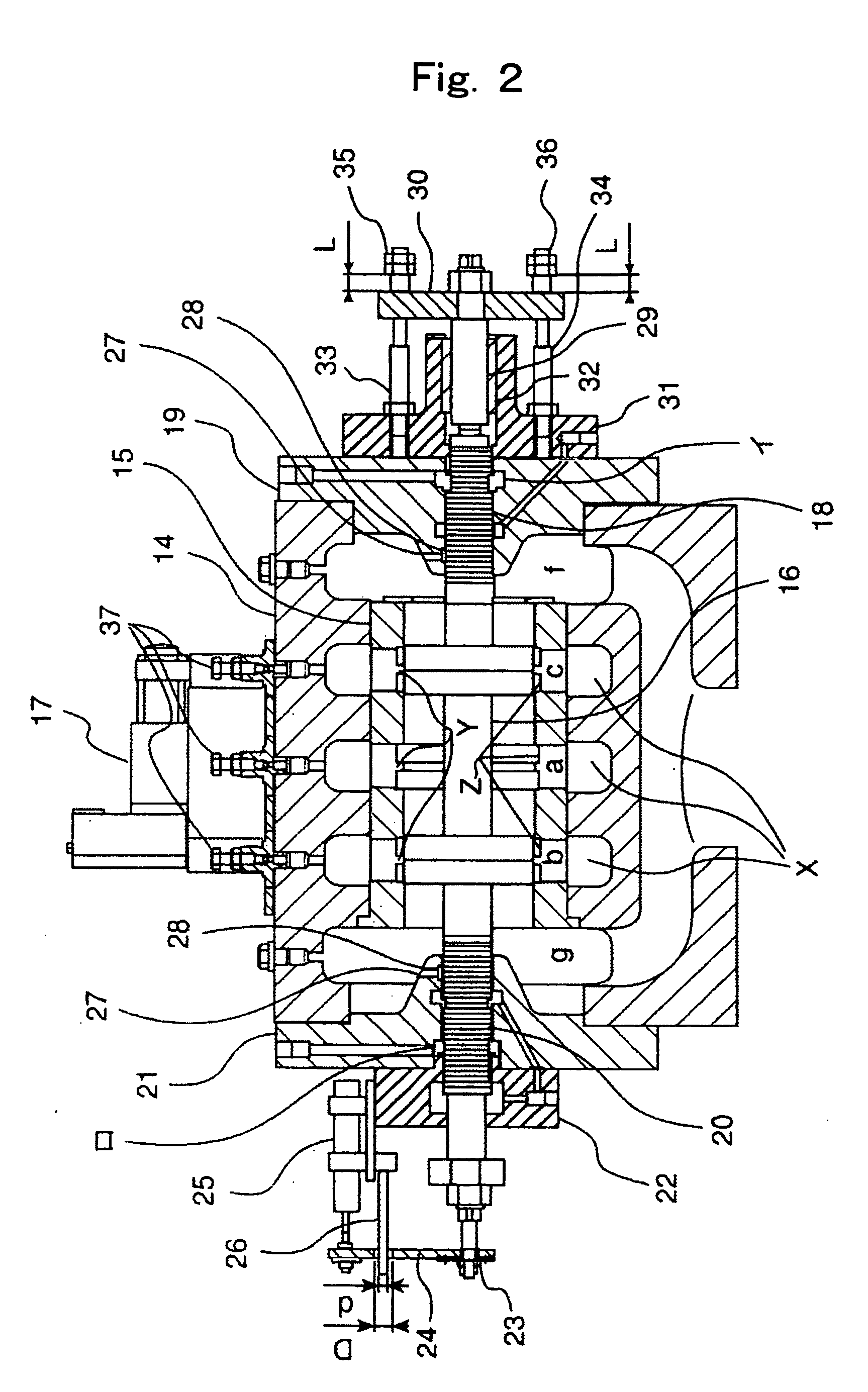
[0016] The invention will be described hereunder by way of embodiments thereof, with reference made to the drawings.

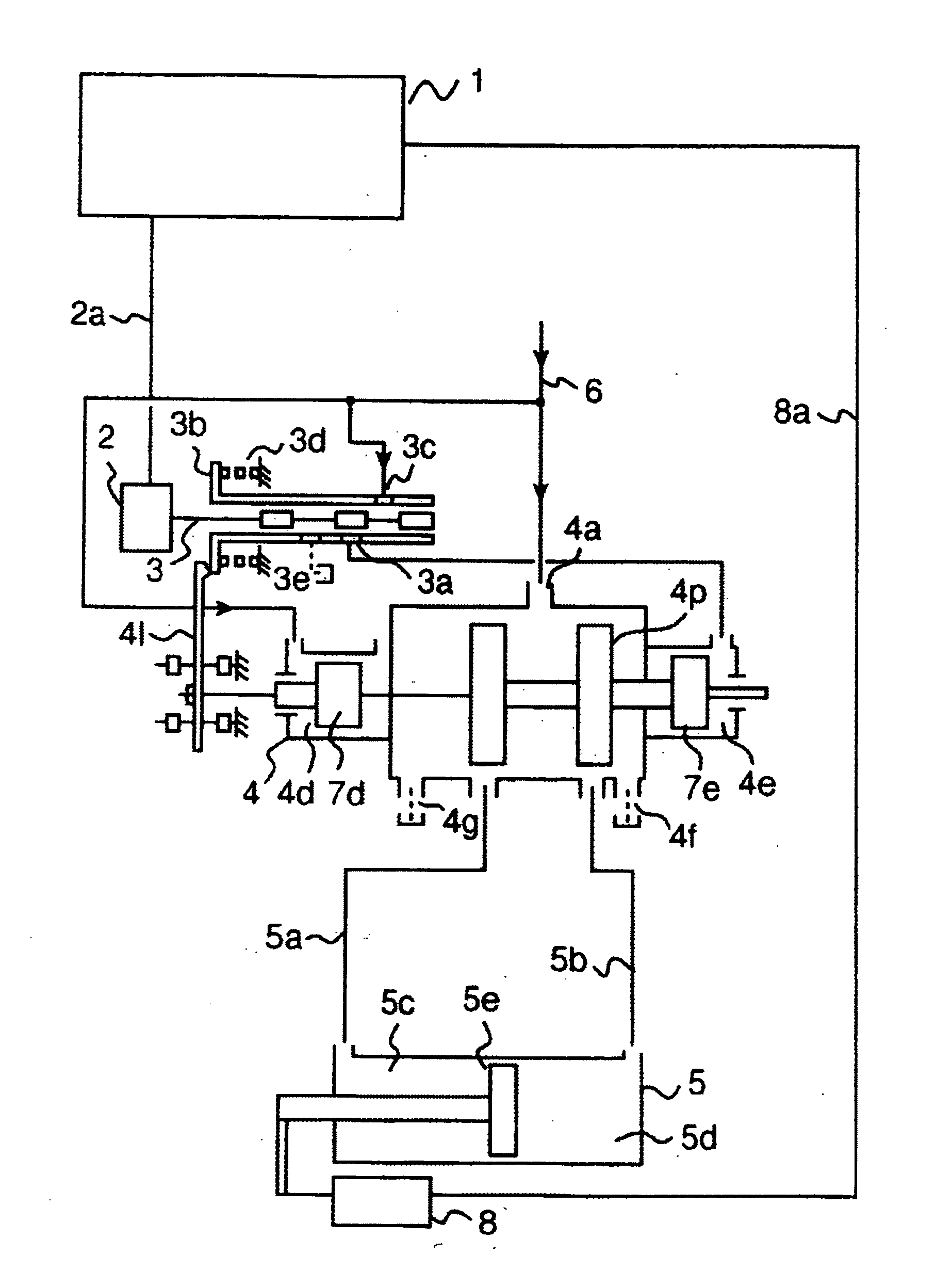
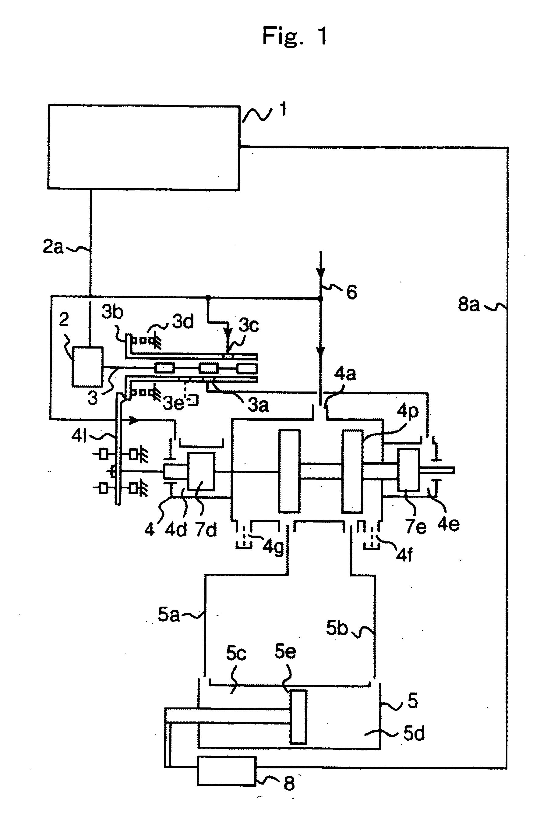
[0017]FIG. 1 shows a schematic diagram of a speed governor for controlling the guide vanes of a hydraulic turbine or a pump turbine installed at a hydraulic power plant.

[0018] A control unit 1 outputs a control signal (control target electric signal) for controlling the guide vanes to an electromechanical transducer 2. The electromechanical transducer 2, which is a converter for turning the electric signal into a mechanical movement, causes a pilot valve 3 directly connected to the electromechanical transducer 2 to move so as to feed the control pressure oil for driving a control piston 7d or 7e to a portion 4d or 4e of a distributing valve 4. For example, when an open-side signal for opening the guide vanes is outputted from the control unit 1, the pilot valve 3 is shifted to the left in the figure by the electromechanical transducer 2. As the pilot valve 3 is shift...


PUM


Abstract

A distributing valve for the speed governor of a hydraulic turbine or the like is provided, which is structured such that air can be vented reliably therefrom. Also provided is a structure of the distributing valve facilitating the machining or assembly of the distributing valve. The distributing valve is structure such that the direction of movement of a plunger 16 of the distributing valve is horizontal, with air vent valves 37 being provided at the highest portion of each of ports a, b, and c of the distributing valve. In addition, the plunger 16 and control pistons 18 and 20 are separately structured, with the control pistons 18 and 20 disposed at either end of the plunger 16. The structure allows the air vent valves 37 to be disposed at the highest portion of the distributing valve, so that air can be vented out of a pressure oil system reliably. Because the structure does not require the high levels of precision in terms of perpendicularity and eccentricity that are required in an integral structure of the plunger 16 and the control pistons 18 and 20, manufacture and assembly of the structure is facilitated.

Description

BACKGROUND OF THE INVENTION [0001] 1. Field of Invention [0002] The present invention relates to the speed governors and distributing valves for hydraulic turbines and pump turbines, and particularly to three-way distributing valves for the speed governor of hydraulic turbines or the like. [0003] 2. Related Art [0004] Three-way distributing valves are used in a speed governor for controlling a hydraulic servomotor driving the guide vanes for adjusting the volume of water that enters a hydraulic turbine or a pump turbine. An example of the three-way distributing valve for the speed governor of hydraulic turbines or pump turbines is disclosed in Patent Document 1, in which a hydraulic amplifier (three-way distributing valve) is disposed such that the plunger (main valve) can be moved vertically. The plunger is driven by a control piston that is vertically moved by pressure oil supplied via a pilot valve. Because the plunger is adapted to be moved up and down by the control piston, the...

Claims


Application Information

Patent Timeline
IPC IPC(8): F15B13/043F15B21/044F03B3/18F03B11/00F03D7/00F15B13/04
CPCF03B3/183F15B13/0402Y02E10/226F15B21/044Y02E10/223F15B13/0435Y10T137/8663Y02E10/20Y02P70/50
Inventor IMAI, HIDEAKI
Owner HITACHI MITSUBISHI HYDRO
Why Eureka
Try Eureka