Polishing apparatus and method

a technology of polishing apparatus and abrasives, which is applied in the direction of lapping machines, manufacturing tools, other manufacturing equipment/tools, etc., can solve the problems of cross contamination, electric resistance, separation of deposited film, etc., and achieve the effect of efficiently polishing the outer peripheral portion of the workpiece and quick polishing operation

Inactive Publication Date: 2005-11-24
TOSHIBA MEMORY CORP
View PDF21 Cites 4 Cited by
  • Summary
  • Abstract
  • Description
  • Claims
  • Application Information

AI Technical Summary

Benefits of technology

[0016] The present invention has been made in view of the above drawbacks; It is therefore a first object of the present invention to provide a polishing apparatus and method which can perform quickly a polishing operation of an outer peripheral portion of a workpiece such as a substrate having a film (particularly metal film) formed thereon as a series of polishing operations accompanying a primary polishing work of a surface of a substrate, and which can polish the outer peripheral portion of the workpiece efficiently.
[0017] A second object of the present invention is to provide an outer periphery polishing apparatus, for polishing an outer peripheral portion of a substrate, which can polish the outer peripheral portion of the substrate efficiently and be of compact construction.
[0020] According to the present invention, polishing of the outer peripheral portion of the workpiece can be quickly conducted by the outer periphery polishing mechanism disposed adjacent to the polishing table as a series of processes before or after a primary polishing of a surface of the workpiece is conducted by the polishing table.
[0022] With the above arrangement, the workpiece is held by the top ring and pressed against the polishing table to thereby conduct a primary polishing of the workpiece, and then the outer peripheral portion of the workpiece is polished by pressing the outer peripheral portion of the workpiece against the outer periphery polishing surface while the workpiece is being held by the top ring. Thereafter, the polished workpiece is transferred to a next process. Further, the outer peripheral portion of the workpiece is polished by bringing the outer peripheral portion of the workpiece into contact with the outer periphery polishing surface over an entire length along a circumferential direction of the workpiece and by rotating the workpiece and the polishing surface relatively to each other, i.e. rotating at least one of the workpiece and the polishing surface. Thus, the outer peripheral portion of the workpiece can be polished efficiently at a low pressure.
[0031] According to the present invention, the outer peripheral portion of the substrate is polished by bringing the outer peripheral portion of the substrate into contact with the outer periphery polishing surface over the entire length along the circumferential direction of the substrate and by rotating the substrate and the polishing surface relatively to each other. Thus, the outer peripheral portion of the substrate can be polished efficiently at a low pressure.
[0039] Thus, the outer peripheral portion of the substrate can be reliably pressed against the polishing surface of the polishing unit at a predetermined pressing force to thus prevent generation of a defective portion due to displacement of the substrate or random movement of the substrate.

Problems solved by technology

However, in recent years, there has been a growing tendency to replace aluminum or aluminum alloys with copper having a low electric resistivity and a high electromigration resistance.
Copper can easily be diffused into an oxide film in a semiconductor fabrication process such as annealing, thus deteriorating the electric insulation of the oxide film and impairing the adhesiveness of the oxide film with a film to be subsequently deposited to possibly cause separation of the deposited film.
Furthermore, copper deposited on the outer peripheral portion of the substrate other than the circuit formation area is not only unnecessary, but may cause cross contamination in subsequent processes of delivering, storing and processing the substrate.
Thus, this polishing work is considerably troublesome.
Further, in this kind of edge polisher, the outer peripheral portion of the substrate (workpiece) is polished while the outer peripheral portion of the substrate is brought into point contact with the polishing surface at a point along a circumferential direction of the substrate, and hence the polishing rate thereof is generally low and it takes much time to complete polishing.

Method used


Image

  • Polishing apparatus and method
  • Polishing apparatus and method
  • Polishing apparatus and method

Examples


Embodiment Construction

[0058] A polishing apparatus and method according to embodiments of the present invention will be described below with reference to drawings.

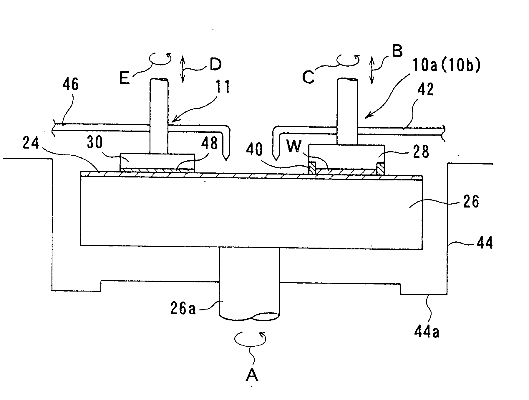
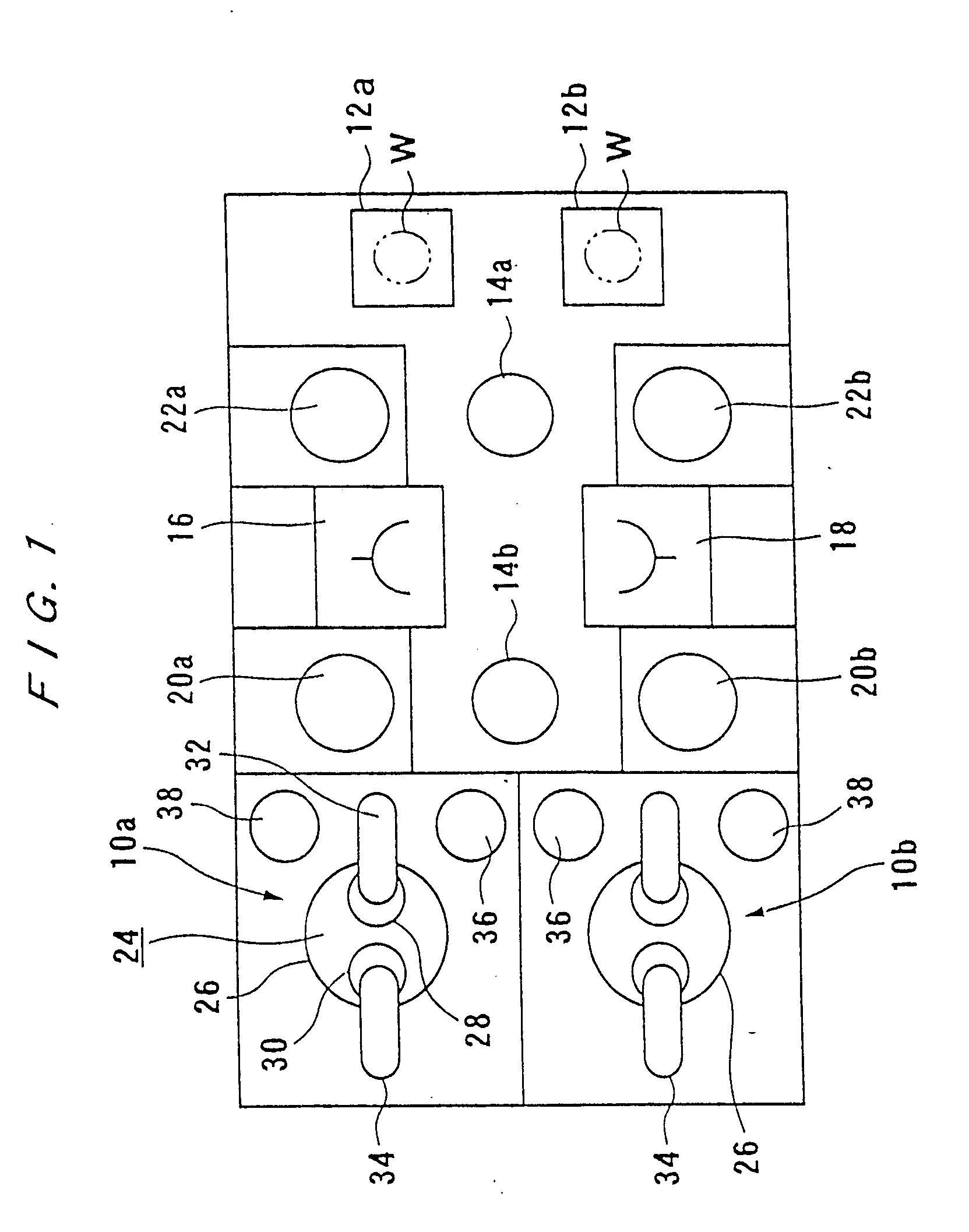
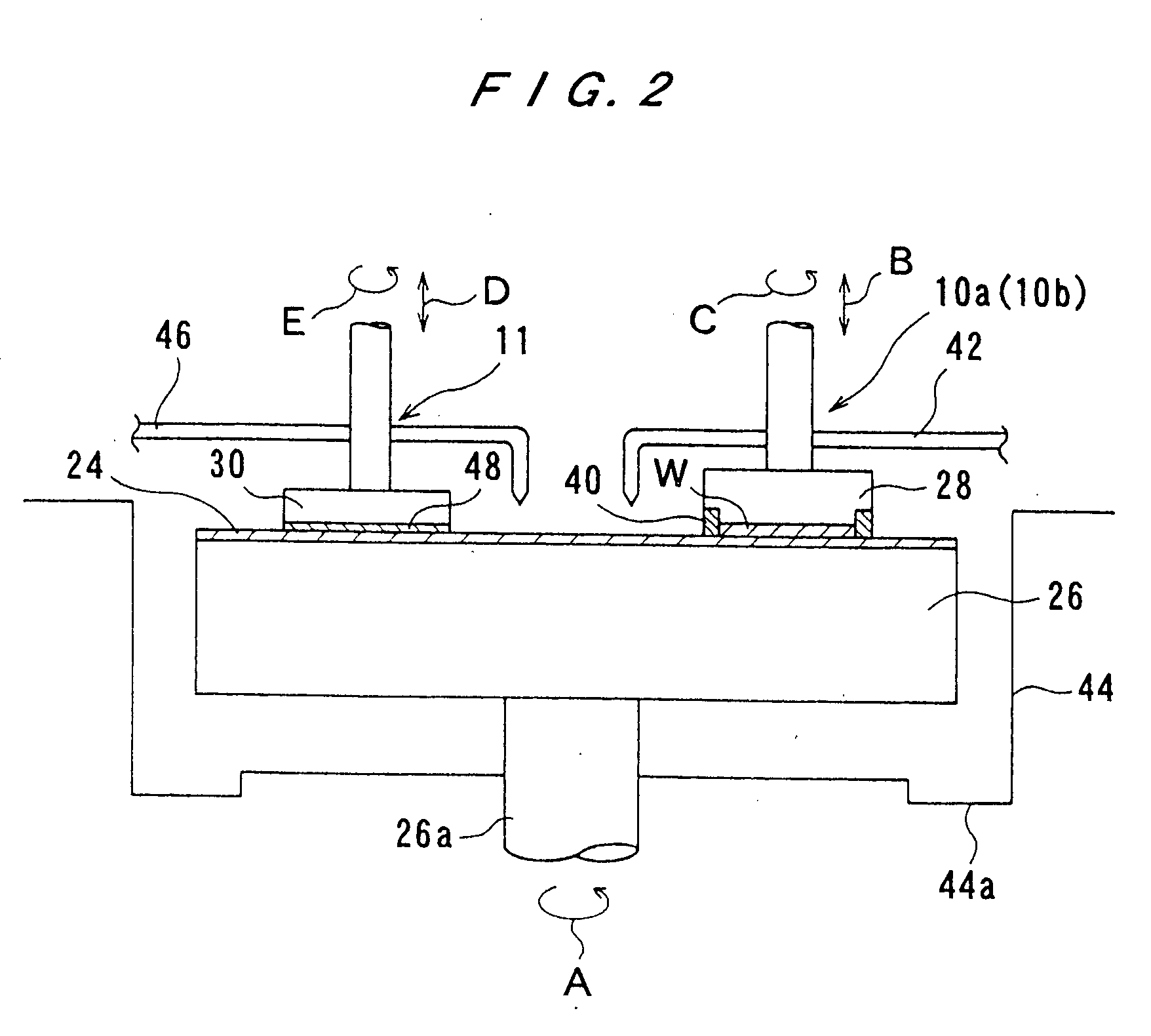
[0059]FIG. 1 shows a layout of the whole structure of the polishing apparatus according to the first embodiment of the present invention. As shown in FIG. 1, a polishing apparatus comprises a pair of polishing units 10a, 10b positioned at one end of a rectangular floor space and spaced from each other in confronting relation to each other, and a pair of loading and unloading units positioned at the other end of the rectangular floor space and having respective wafer cassettes 12a, 12b spaced from the polishing units 10a, 10b in confronting relation thereto. The wafer cassettes 12a, 12b house copper interconnect substrates (workpieces to be polished) in which circuits are formed at areas except for outer peripheral portions of the respective substrates and copper is deposited on substantially entire surfaces of the respective substrates. Two tr...


PUM

PropertyMeasurementUnit
centrifugal forceaaaaaaaaaa
electric resistivityaaaaaaaaaa
electromigration resistanceaaaaaaaaaa

Abstract

A polishing apparatus and method has a function of polishing a surface of a film formed on a substrate to a flat mirror finish and a function of polishing unnecessary metal film such as copper film deposited on an outer peripheral portion of the substrate to remove such unnecessary metal film. The polishing apparatus comprises a surface polishing mechanism comprising a polishing table having a polishing surface and a top ring for holding the substrate and pressing the substrate against the polishing surface of the polishing table to thereby polish a surface of the substrate, and an outer periphery polishing mechanism for polishing an outer peripheral portion of the substrate.

Description

[0001] This is a Divisional application of U.S. application Ser. No. 09 / 824,644, filed Apr. 4, 2001;BACKGROUND OF THE INVENTION [0002] 1. Field of the Invention [0003] The present invention relates to a polishing apparatus and method for polishing a surface of a workpiece such as a semiconductor wafer, and more particularly to a polishing apparatus and method having a function of polishing a surface of a film formed on a substrate to a flat mirror finish and a function of polishing unnecessary metal film or the like, particularly copper (Cu) film, deposited on an outer peripheral portion of the substrate to remove such unnecessary metal film. The present invention also relates to an outer periphery polishing apparatus for polishing an outer peripheral portion of a substrate to remove unnecessary metal film or the like deposited on the outer peripheral portion of the substrate. [0004] 2. Description of the Related Art [0005] Generally, aluminum or aluminum alloys have been used as a ...

Claims


Application Information

Patent Timeline
Patent Type & Authority Applications(United States)
IPC IPC(8): B24B9/06B24B37/12B24B37/34H01L21/00
CPCB24B9/065H01L21/67046B24B37/345B24B37/12
Inventor KIMURA, NORIOSHIRAKASHI, MITSUHIKOOKUMURA, KATSUYAISHII, YOUKUNISAWA, JUNJIYANO, HIROYUKI
Owner TOSHIBA MEMORY CORP
Why Eureka
Try Eureka