Liquid crystal display and method of manufacturing the same

a technology of liquid crystal display and liquid crystal, which is applied in the field of liquid crystal display, can solve the problems of high power consumption, significant reduction in visibility, and low power consumption, and achieve the effect of high display characteristics

Active Publication Date: 2005-12-01
AU OPTRONICS CORP
View PDF13 Cites 59 Cited by
  • Summary
  • Abstract
  • Description
  • Claims
  • Application Information

AI Technical Summary

Benefits of technology

[0024] The invention makes it possible to provide a transflective liquid crystal display whi

Problems solved by technology

Among active matrix type liquid crystal displays, attention is recently paid to reflective liquid crystal displays which can be provided with a light weight and a small thickness and which consume low power.
However, a one-polarizer type reflective liquid crystal display has a problem in that it undergoes a significant reduction in visibility in an environment of low brightness because the visibility of the display significantly depends on the brightness of the surroundings.
Meanwhile, a transmissive liquid crystal display is characterized in that it exhibits high contrast and visibility even in a dark environment although it consumes high power because of the use a backlight unit as a light source.
However, a transmissive liquid crystal display has a problem in that it undergoes a significant reduction in visibility and therefore becomes poorer in display quality than a reflective liquid crystal display in a bright environment.
However, a front-light type liquid crystal display has a problem in that it has a contrast ratio lower than that of a transmissive liquid crystal display in a dark environment and in that it displays an object darker than a normal reflective liquid crystal display does in a bright environment due to absorption of light at a light guide plate of the front-light unit.
A metal thin film has a prob

Method used


Image

  • Liquid crystal display and method of manufacturing the same
  • Liquid crystal display and method of manufacturing the same
  • Liquid crystal display and method of manufacturing the same

Examples


embodiment 1-1

[0059] A liquid crystal display according to Embodiment 1-1 and a liquid crystal display as an example comparative to the same were fabricated. First, a liquid crystal display as a comparative example shown in FIG. 5 was fabricated as follows. As shown in FIG. 5, an aluminum (Al) film was formed using sputtering on an entire surface of a transparent electrode 16 and was patterned to form a reflective electrode 17 in the area shown on the right half of the figure. Next, alignment films 36 and 37 were formed, through coating, on entire surfaces of a TFT substrate 2 and an opposite substrate 4, respectively using a polyamic acid material manufactured by JSR Corp. The substrates 2 and 4 were rubbed in predetermined respective rubbing directions to achieve anti-parallel rubbing, and the substrates 2 and 4 were combined to fabricate an open cell. A negative nematic liquid crystal manufactured by Merck KGaA was injected in the open cell. The cell thickness was set at 4.2 μm.

[0060] Next, t...

embodiment 1-2

[0062] A liquid crystal display according to Embodiment 1-2 and a liquid crystal display as an example comparative to the same were fabricated. In the present embodiment and the comparative example, a color filter (CF) layer 40 was formed on a glass substrate 11 forming a part of an opposite substrate 4. Light passes through the CF layer 40 only once during display in the transmissive mode, whereas light passes through the CF layer 40 twice during display in the reflective mode. Therefore, the CF layer 40 is formed with a thickness d1 in a transmissive area T and formed with a thickness d2 that is about one-half of the thickness d1 in a reflective area R (see FIG. 7). The substrates 2 and 4 were rubbed on an anti-parallel rubbing basis in a manner similar to that in Embodiment 1-1, and the substrates 2 and 4 were combined to fabricate an open cell. A negative nematic liquid crystal manufactured by Merck KGaA was injected in the open cell to fabricate the liquid crystal display as a ...

embodiment 1-3

[0065]FIGS. 8A to 8C show a method of manufacturing a liquid crystal display according to Embodiment 1-3. In the present embodiment, as shown in FIG. 8A, linear protrusions 44 (banks) 44 were formed using a resist instead of applying and forming alignment films 36 and 37 in the transmissive area T. The reflective area R was not rubbed, although alignment films 36 and 37 were formed thereon through coating. The substrates 2 and 4 were combined with each other to leave a cell thickness of 4.2 μm in the transmissive area T, and an open cell was thus fabricated.

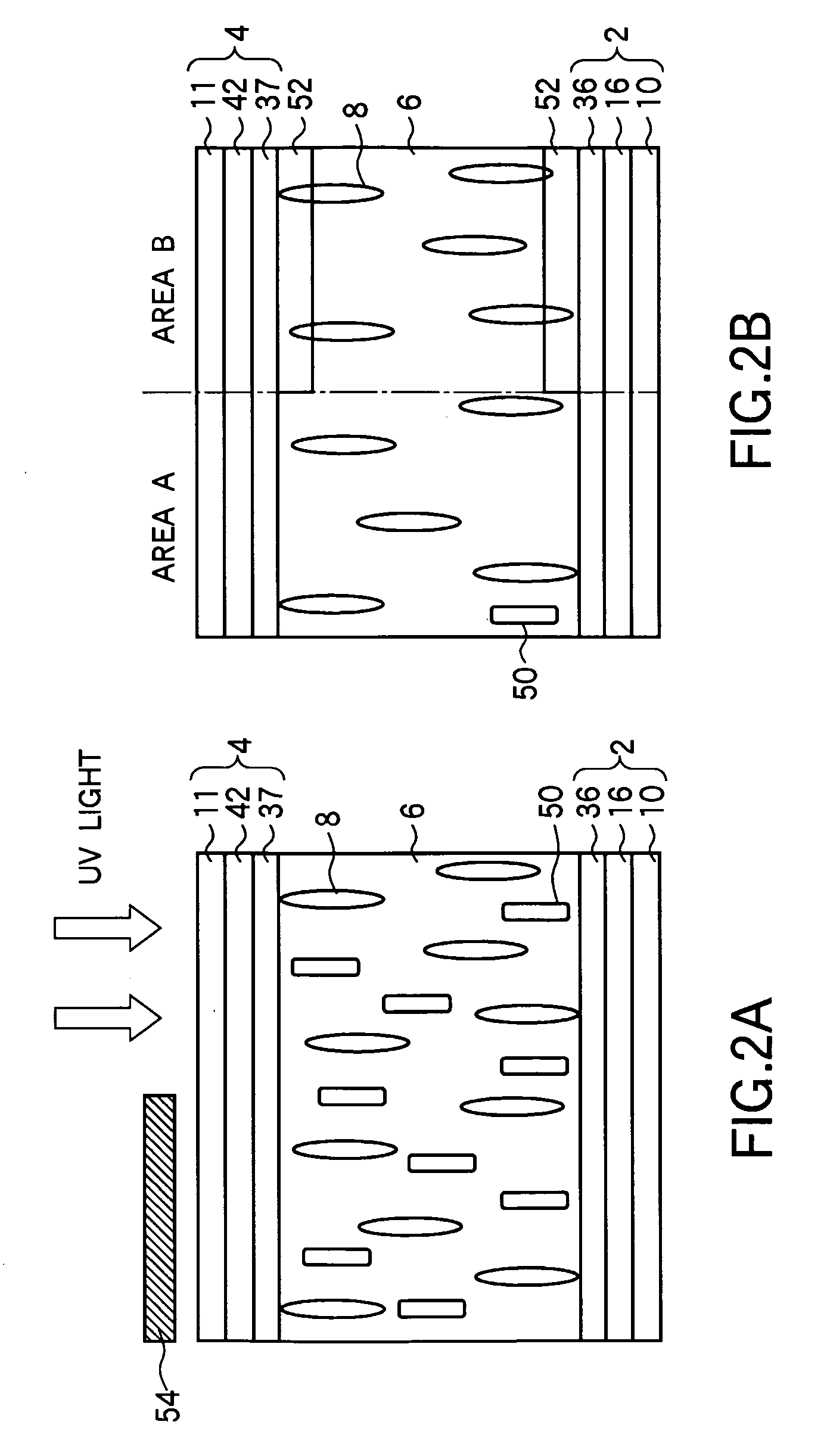
[0066] Next, a liquid crystal added with 0.8 wt % mixture of a photo-polymeric bifunctional monomer and a monofunctional monomer having an alkyl chain was injected in the open cell. Next, UV light incident upon the substrate surface substantially perpendicularly thereto was radiated from the side of the TFT substrate 2. The UV light had irradiation intensity of 2 mW / cm2 and irradiation energy of 9000 mJ / cm2. FIG. 8B shows the st...


PUM


Abstract

The invention relates to a transflective liquid crystal display and a method of manufacturing the same and provides a transflective liquid crystal display which can achieve high display characteristics in both of reflective and transmissive modes and a method of manufacturing the same. The display has a pair of substrates provided opposite to each other, a liquid crystal sealed between the pair of substrates, a plurality of pixel regions each having a reflective area which reflects light from the side of one of the substrates and a transmissive area which transmits light from the side of the other of the substrates toward the one of the substrates, and an ultraviolet-hardened material which is a product of polymerization of a polymeric component mixed in the liquid crystal with ultraviolet light and which is formed at a substrate interface in the reflective area to control the alignment of the liquid crystal in the reflective area.

Description

BACKGROUND OF THE INVENTION [0001] 1. Field of the Invention [0002] The present invention relates to a liquid crystal display and a method of manufacturing the same and, more particularly, to a transflective liquid crystal display capable of display in both reflective and transmissive modes and a method of manufacturing the same. [0003] 2. Description of the Related Art [0004] Among active matrix type liquid crystal displays, attention is recently paid to reflective liquid crystal displays which can be provided with a light weight and a small thickness and which consume low power. Reflective liquid crystal displays that are currently in practical use are one-polarizer type displays utilizing a TN (Twisted Nematic) mode liquid crystal (see Patent Documents 1 and 2 for example). However, a one-polarizer type reflective liquid crystal display has a problem in that it undergoes a significant reduction in visibility in an environment of low brightness because the visibility of the displa...

Claims


Application Information

Patent Timeline
IPC IPC(8): G02F1/1335G02F1/1337G02F1/1343
CPCG02F1/133555G02F2001/133761G02F1/133788G02F1/133761G02F1/1337G02F1/1335
Inventor KATAOKA, SHINGOOHMURO, KATSUFUMISASAKI, TAKAHIROTASHIRO, KUNIHIRO
Owner AU OPTRONICS CORP
Why Eureka
Try Eureka