
Liquid crystal display device and method of producing the same

a display device and liquid crystal technology, applied in the direction of instruments, chemistry apparatus and processes, transportation and packaging, etc., can solve the problems of poor viewing angle characteristics of the display device of the tn mode, increase the cost of the member, and reduce the production. , to achieve the effect of good liquid crystal alignment and reduction of production costs

Active Publication Date: 2005-12-01
AU OPTRONICS CORP
View PDF16 Cites 63 Cited by
  • Summary
  • Abstract
  • Description
  • Claims
  • Application Information

AI Technical Summary

Benefits of technology

[0015] It is an object of the present invention to provide a liquid crystal display device which is capable of further decreasing the cost of production yet obtaining a good liquid crystal alignment, and a method of producing the same.
[0016] It is another object of the present invention to provide a liquid crystal display device capable of obtaining a good liquid crystal alignment despite of the use of a mother glass of a large size and a substrate of a special shape, and a method of producing the same.
[0021] According to the invention, a liquid crystal display device at a further decreased cost of production yet maintaining a good liquid crystal alignment can be realized. Further, according to the invention, a liquid crystal display device capable of maintaining a good liquid crystal alignment despite of the use of a mother glass of a large size and substrates of a special shape can be realized.

Problems solved by technology

However, the liquid crystal display device of the TN mode is accompanied by a problem of poor viewing angle characteristics, and study has been conducted extensively to improve the viewing angle characteristics.
Due to the irregular film thickness and infiltration of foreign matter in the step of printing the alignment film, therefore, the yield of production decreases, the cost of members increases and the tact time lengthens.
As described above, the conventional liquid crystal display device of the MVA system still involves a problem of an increase in the cost of production due to the step of printing the alignment film.
However, the device for printing the alignment film cannot be easily modified to respond to the mother glasses of very large sizes.
It is quite difficult to print the alignment film on these substrates.
Therefore, the liquid crystal display devices using the mother glasses of large sizes and substrates of special shapes are accompanied by a problem of difficulty in obtaining a good liquid crystal alignment.

Method used


Image

  • Liquid crystal display device and method of producing the same
  • Liquid crystal display device and method of producing the same
  • Liquid crystal display device and method of producing the same

Examples


first embodiment

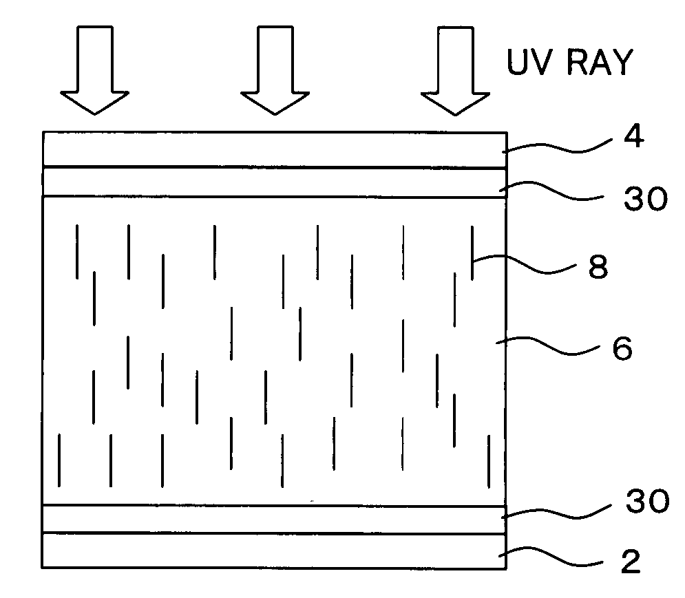
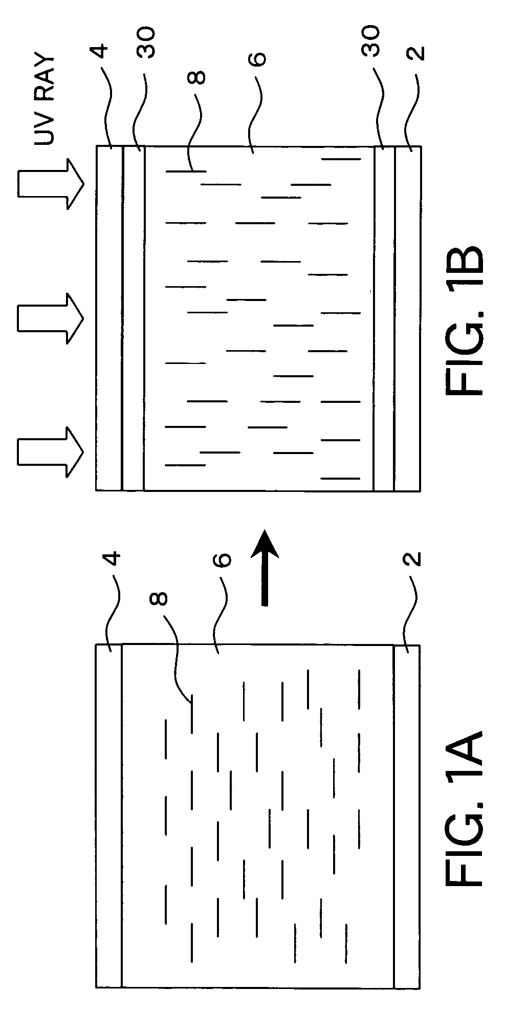
[0043] A liquid crystal display device and a method of its production according to a first embodiment of the invention will now be described with reference to FIGS. 1 to 9. FIG. 1 schematically illustrates the constitution of a liquid crystal display device and a method of its production according to the embodiment. Referring, first, to FIG. 1A, liquid crystals 6 into which a polymerizable component is mixed and having a negative dielectric anisotropy are sealed between a pair of substrates 2 and 4. In this embodiment, the substrates 2 and 4 have not been coated with a vertical alignment film. Therefore, the liquid crystal molecules 8 in this step are aligned nearly in parallel with the substrate surfaces. Referring next to FIG. 1B, the liquid crystals 6 are irradiated with an ultraviolet ray (or visible ray) to polymerize the polymerizable component. The polymerizable component contains a polyfunctional monomer having a symmetrical structure. Therefore, an ultraviolet ray-cured pro...

example 1-1

[0068] A lauryl acrylate was dissolved at a mass mol concentration of 1.3×10⁻⁴ mols / g in the negative-type liquid crystals A manufactured by Merck Ltd. Next, a bifunctional monomer was dissolved at a concentration of 1.3×10⁻⁵ mols / g which was one-tenth of the above mass mol concentration in the liquid crystals in which the lauryl acrylate had been dissolved to prepare mixed liquid crystals. Eight kinds of bifunctional monomers a to h shown in FIGS. 3A to 3H were used to prepare eight kinds of mixed liquid crystals. Further, pairs of glass substrates forming electrodes of ITO were so stuck together that the cell thickness was 4.25 μm thereby to prepare a plurality of empty cells. No alignment film was formed on the two glass substrates. Next, the eight kinds of mixed liquid crystals were injected into the empty cells respectively and were sealed to prepare eight kinds of evaluation cells. Thereafter, the mixed liquid crystals of the evaluation cells were irradiated with an ultraviole...

example 1-2

[0072] A lauryl acrylate was dissolved at a mass mol concentration of 1.3×10⁻⁴ mols / g in the negative-type liquid crystals A manufactured by Merck Ltd. Next, a bifunctional monomer was dissolved at a concentration of 1.3×10⁻⁵ mols / g which was one-tenth of the above mass mol concentration in the liquid crystals in which the lauryl acrylate has been dissolved to prepare mixed liquid crystals. As the bifunctional monomers, there were used the monomer (a) shown in FIG. 3A and the monomers (i) to (k) shown in FIGS. 4A to 4C respectively to prepare four kinds of mixed liquid crystals. Further, a pair of glass substrates forming electrodes of ITO were stuck together so that the cell thickness was 4.25 μm thereby to prepare a plurality of empty cells. No alignment film was formed on the two glass substrates. Next, the four kinds of mixed liquid crystals were injected into the respective empty cells and were sealed to prepare evaluation cells in a plurality of numbers for each kind of the mi...


PUM

PropertyMeasurementUnit
wavelengthaaaaaaaaaa
wavelengthsaaaaaaaaaa
wavelength regionaaaaaaaaaa

Abstract

A liquid crystal display device which is capable of further decreasing the cost of production yet obtaining a good liquid crystal alignment, and a method of producing the same. The liquid crystal display device comprises a pair of substrates arranged facing each other; a liquid crystal sealed between the substrates; and an ultraviolet ray-cured product for controlling the alignment of the liquid crystal. The ultraviolet ray-cured product is formed near the interfaces to the substrates by polymerizing a polymerizable component mixed in the liquid crystal with light. The polymerizable component contains a polyfunctional monomer having a symmetrical structure, and the ultraviolet ray-cured product has a side-chain structure.

Description

BACKGROUND OF THE INVENTION [0001] 1. Field of the Invention [0002] The present invention relates to a liquid crystal display device and a method of producing the same. More particularly, the invention relates to a liquid crystal display device of the type of vertical alignment in which the liquid crystal molecules are aligned nearly vertically to the surfaces of the substrates when no voltage is applied and a method of producing the same. [0003] 2. Description of the Related Art [0004] As the active matrix type liquid crystal display device (LCD), there has heretofore been widely used a liquid crystal display device of a TN (twisted nematic) mode in which a liquid crystal material having a positive dielectric anisotropy is aligned horizontally to the substrate surfaces and being twisted by 90 degrees between the opposing substrates. However, the liquid crystal display device of the TN mode is accompanied by a problem of poor viewing angle characteristics, and study has been conduct...

Claims


Application Information

Patent Timeline
Patent Type & Authority Applications(United States)
IPC IPC(8): C09K19/00C09K19/56G02F1/1337
CPCC09K19/56G02F1/133711Y10T428/1036Y10T428/10Y10T428/1005G02F1/133788C09K2323/02C09K2323/03C09K2323/00H01H13/14H01H2231/026
Inventor KATAOKA, SHINGOOHMURO, KATSUFUMITSUDA, HIDEAKIHIROSAWA, JIN
Owner AU OPTRONICS CORP
Features
  • Generate Ideas
  • Intellectual Property
  • Life Sciences
  • Materials
  • Tech Scout
  • Unparalleled Data Quality
  • Higher Quality Content
  • 60% Fewer Hallucinations
Learn More