Differetial thermal sensors

a technology of differential fluid properties and thermal sensors, applied in the direction of instruments, testing water, material analysis, etc., can solve the problems of undesired error components, two thermal conductivity sensors in this system may be exposed to different conditions, and achieve the effect of maximum differential fluid property measurement sensitivity and time resolution

Inactive Publication Date: 2005-12-01
HONEYWELL INT INC
View PDF17 Cites 47 Cited by
  • Summary
  • Abstract
  • Description
  • Claims
  • Application Information

AI Technical Summary

Benefits of technology

[0012] According to still another aspect of the present invention, a differential thermal conductivity sensor comprises a housing and first and second microstructures. The housing has a channel exposed to a fluid whose thermal conductivity is to be determined. The first microstructure sensor is mounted to the housing so as to be exposed to the fluid in the channel, and the first microstructure sensor includes a microheater and at least one temperature responsive microsensor. The second microstructure sensor is mounted to the housing so as to be exposed to the fluid in the channel, the second microstructure sensor includes a microheater and at least one temperature responsive microsensor, the two channels are precisely of the same shape, and the first and second microstructure sensors are mounted to the housing so that there is a minimum distance between the first and second microstructure sensors and the channel as well as a minimum dead volume around each individual sensor so as to maximize differential fluid property measurement sensitivity and time resolution, with least interference by uncontrolled differences in temperature, pressure, fluid velocity, orientation and acceleration.

Problems solved by technology

Thermal conductivity sensors available today for performing the above functions are bulky and expensive.
However, these present absolute thermal conductivity sensors also respond to changes in temperature, pressure, orientation, acceleration, vibration, rotation, and flow, which is generally an undesirable response of these absolute thermal conductivity sensors.
However reducing the undesirable influence of temperature, pressure, humidity, orientation, or rotation typically requires the use of additional temperature, pressure, and / or orientation sensors.
However, the two thermal conductivity sensors in this system may be exposed to different, but steady pressures due to the pressure drop through the separation column of the gas chromatography system.
Thus, such gas chromatography systems produce outputs that contain an undesired error component due to this pressure drop.
Moreover, available differential thermal conductivity sensors used in these systems are typically manufactured in low volumes, with specially designed hot wire anemometers which result in the systems being very costly.

Method used


Image

  • Differetial thermal sensors
  • Differetial thermal sensors
  • Differetial thermal sensors

Examples


first embodiment

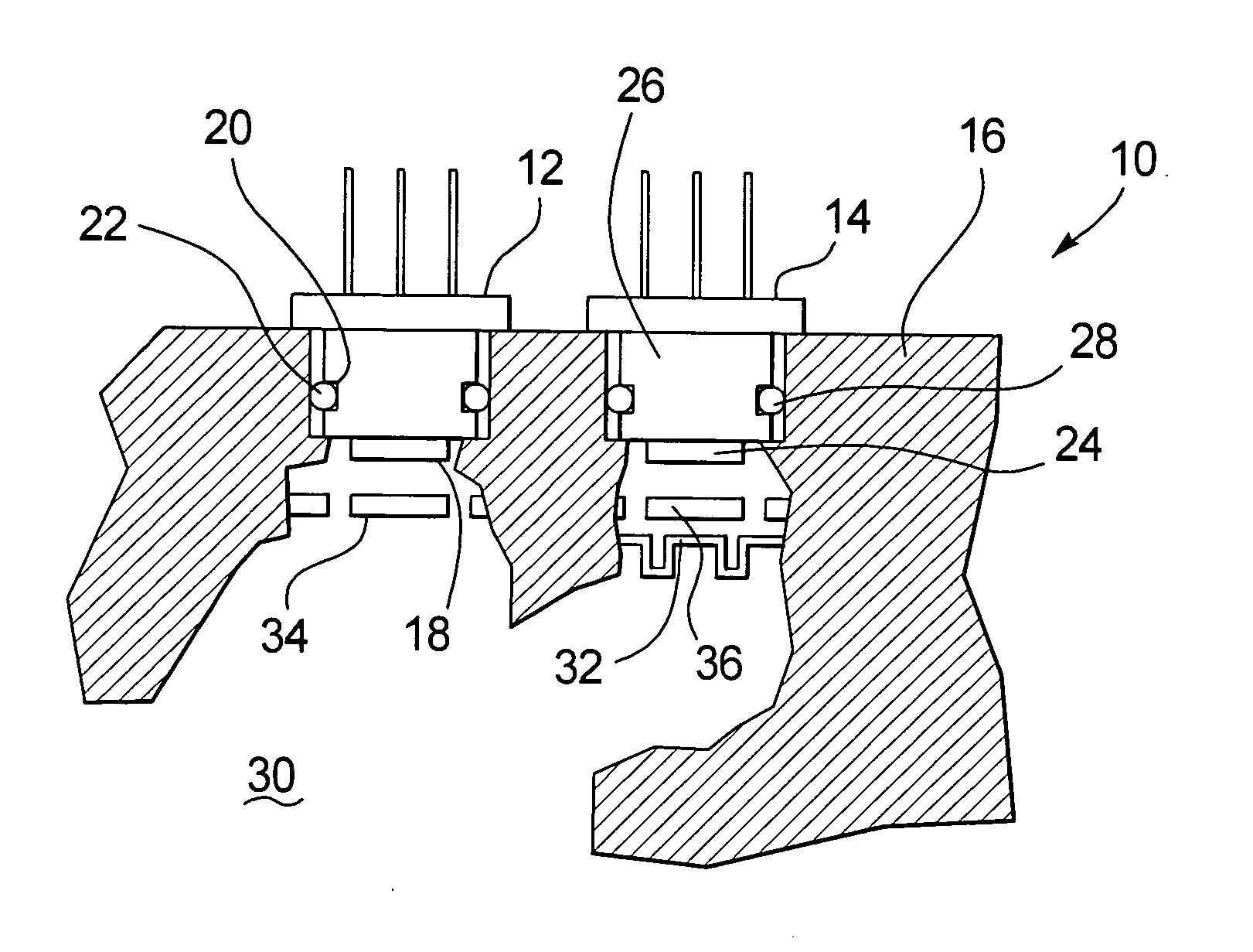
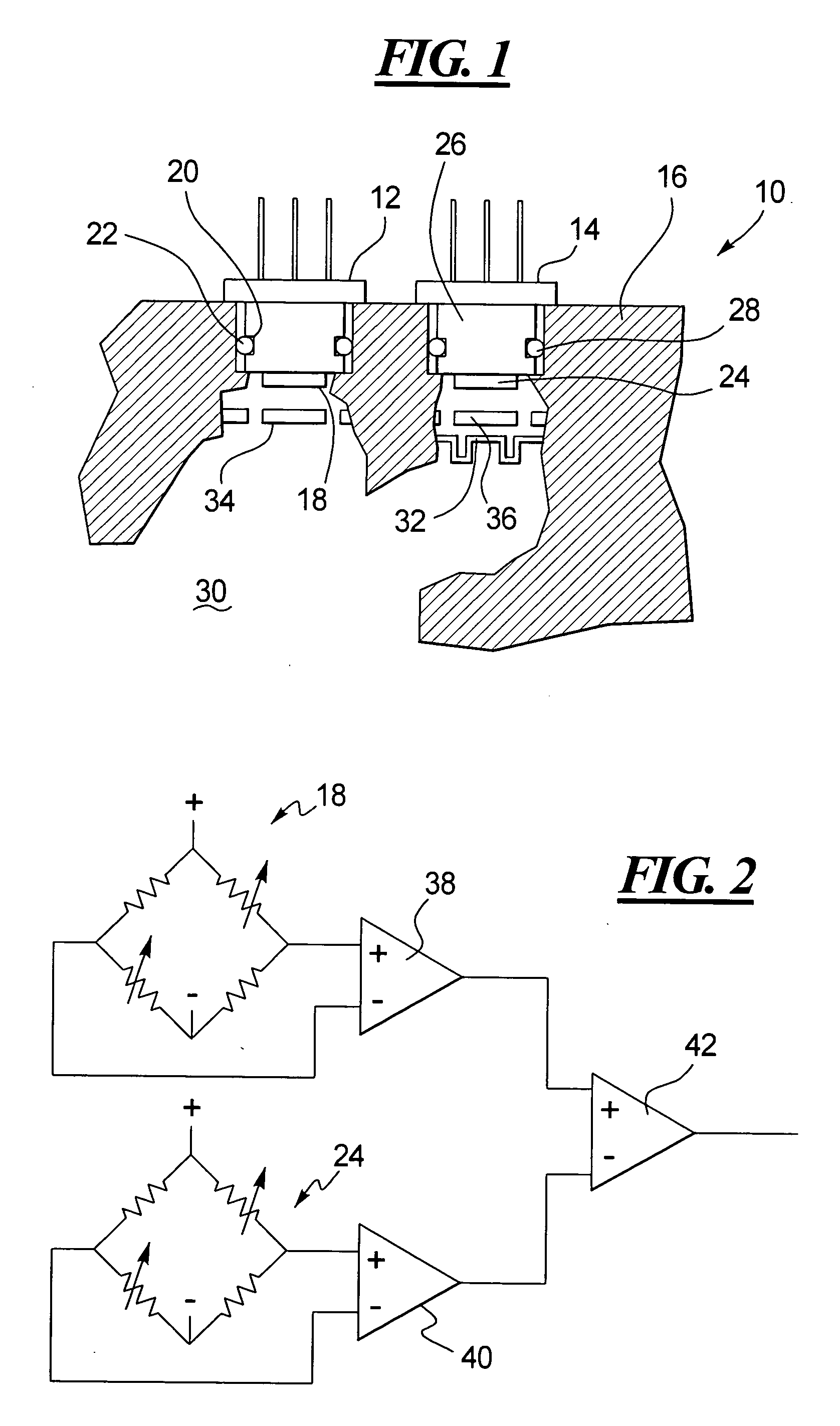
[0022]FIG. 1 shows an absolute thermal conductivity sensor 10 according to the present invention. As shown in FIG. 1, the absolute thermal conductivity sensor 10 includes a first microstructure sensor 12 and a second microstructure sensor 14 mounted to a housing 16.

[0023] The first microstructure sensor 12, for example, may comprise a first microstructure 18 supported by a first mounting block 20 secured to the housing 16. A first O-ring seal 22 fitted in a recess of the first mounting block 20 seals against leakage between the housing 16 and the first mounting block 20.

[0024] The second microstructure sensor 14, for example, may comprise a second microstructure 24 supported by a second mounting block 26 secured to the housing 16. A second O-ring seal 28 fitted in a recess of the second mounting block 26 seals against leakage between the housing 16 and the second mounting block 26.

[0025] Each of the first and second microstructures 18 and 24, for example, may be constructed in acc...

second embodiment

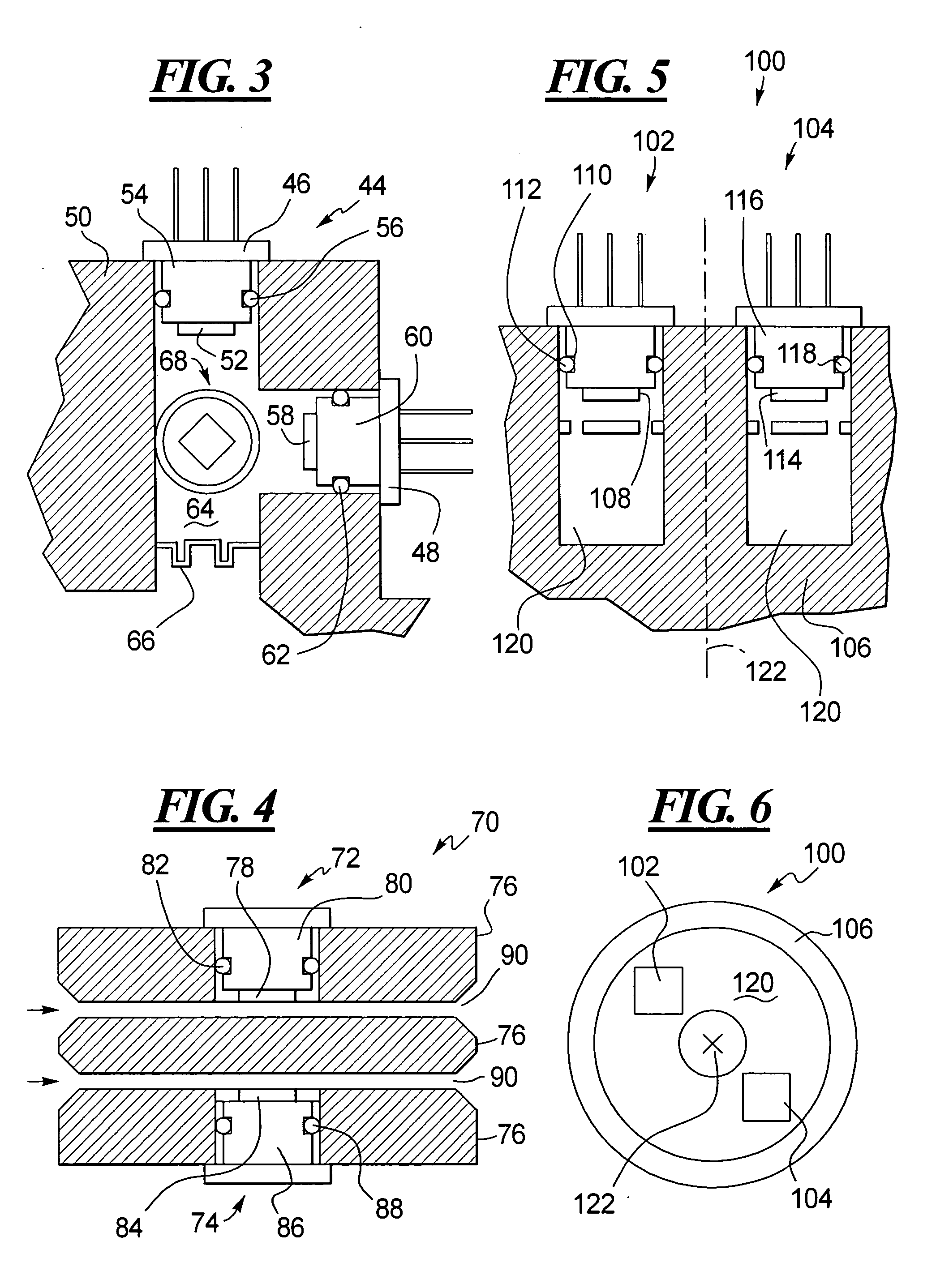
[0033]FIG. 3 shows an orientation sensor 44 according to the present invention. As shown in FIG. 3, the orientation sensor 44 includes a first microstructure sensor 46 and a second microstructure sensor 48 mounted to a housing 50.

[0034] The first microstructure sensor 46, for example, may comprise a first microstructure 52 supported by a first mounting block 54 secured to the housing 50. A first O-ring seal 56 fitted in a recess of the first mounting block 54 seals against leakage between the housing 50 and the first mounting block 54.

[0035] The second microstructure sensor 48, for example, may comprise a second microstructure 58 supported by a second mounting block 60 secured to the housing 50. A second O-ring seal 62 fitted in a recess of the second mounting block 60 seals against leakage between the housing 50 and the second mounting block 60.

[0036] Each of the first and second microstructures 52 and 58, for example, may be constructed in accordance with the microbridge disclos...

third embodiment

[0043]FIG. 4 shows a differential thermal conductivity sensor 70 according to the present invention. For example, the differential thermal conductivity sensor 70 can be used in gas chromatography. As shown in FIG. 4, the differential thermal conductivity sensor 70 includes a first microstructure sensor 72 and a second microstructure sensor 74 mounted to a housing 76.

[0044] The first microstructure sensor 72, for example, may comprise a first microstructure 78 supported by a first mounting block 80 secured to the housing 76. A first O-ring seal 82 fitted in a recess of the first mounting block 80 seals against leakage between the housing 76 and the first mounting block 80.

[0045] The second microstructure sensor 74, for example, may comprise a second microstructure 84 supported by a second mounting block 86 secured to the housing 76. A second O-ring seal 88 fitted in a recess of the second mounting block 86 seals against leakage between the housing 76 and the second mounting block 86...


PUM

PropertyMeasurementUnit
dead volumeaaaaaaaaaa
absolute thermal conductivityaaaaaaaaaa
temperatureaaaaaaaaaa

Abstract

A sensor includes at least two microsensor chips in a housing. The chips may be arranged as (i) an absolute thermal conductivity sensor by exposing one chip to a sample fluid and the other chip to a sealed reference fluid, (ii) a differential thermal conductivity sensor by exposing the two chips to a sample fluid before and after it is modified, respectively, (iii) a one-axis rotation sensor by exposing both chips, positioned at an angle of 180° relative to one another, to a rotational flow in a toroidal chamber, (iv) a two or three axis rotation sensor by placing the two chips or three such chips on two or three orthogonal faces of a cube, (v) a one axis orientation / tilt / acceleration sensor by exposing the two chips to a fluid in a sealed toroidal chamber and by mounting the chips at an angle of substantially 90° relative to one another, (vi) a two axis orientation / tilt / acceleration sensor by placing the two chips at an angle of 90° relative to one another in a fluid filled chamber substantially without inertial flow, and (vii) a combined tilt / rotation sensor based on above (iii) by periodically adding and subtracting the signals from the two chips.

Description

TECHNICAL FIELD OF THE INVENTION [0001] The present invention relates to the design and use of one type of thermal sensor building block for the creation of environmentally compensated sensor system embodiments of absolute and relative thermal conductivity, rotation and 1-to-3-axis tilt or acceleration. BACKGROUND OF THE INVENTION [0002] Thermal sensors that sense the thermal conductivity of a material such as a fluid have been used in a variety of applications including gas chromatography. [0003] In gas chromatography, an unknown gas sample volume is injected into a carrier gas, the unknown gas is separated by the action of a separating column, and the separated sample gas components are transported by the carrier gas to and past a sensor, such as the thermal conductivity sensor, that senses changes in thermal conductivity inherent in the various components of the unknown gas. The thermal conductivity sensor responds to any component of the unknown gas whose thermal conductivity is...

Claims


Application Information

Patent Timeline
Patent Type & Authority Applications(United States)
IPC IPC(8): G01N25/18G01N27/18G01N30/66G01P15/00
CPCG01N25/18G01P15/008G01N30/66G01N27/18
Inventor BONNE, ULRICH
Owner HONEYWELL INT INC
Why Eureka
Try Eureka