

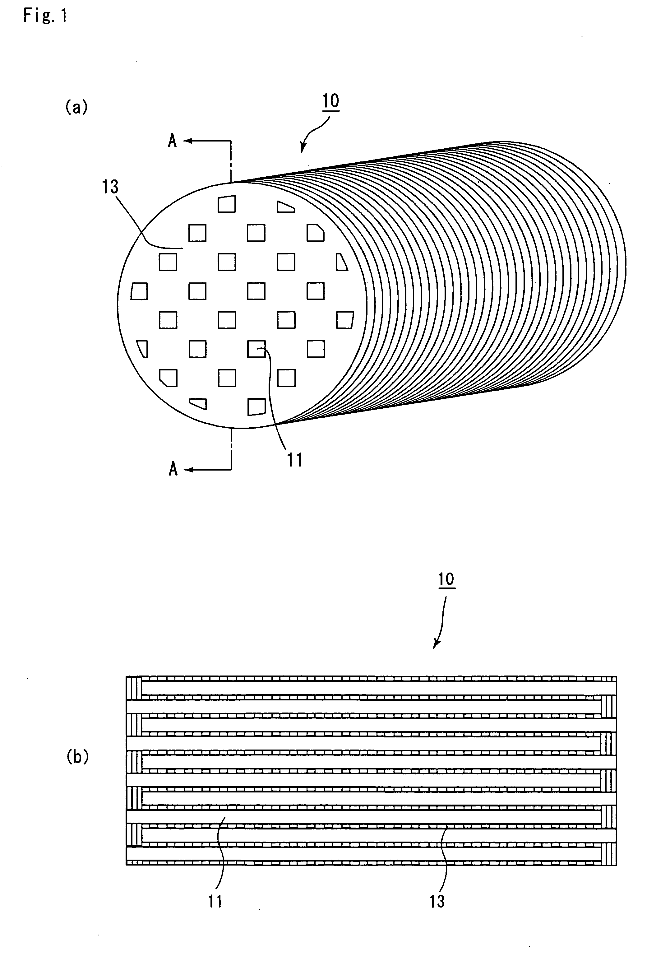
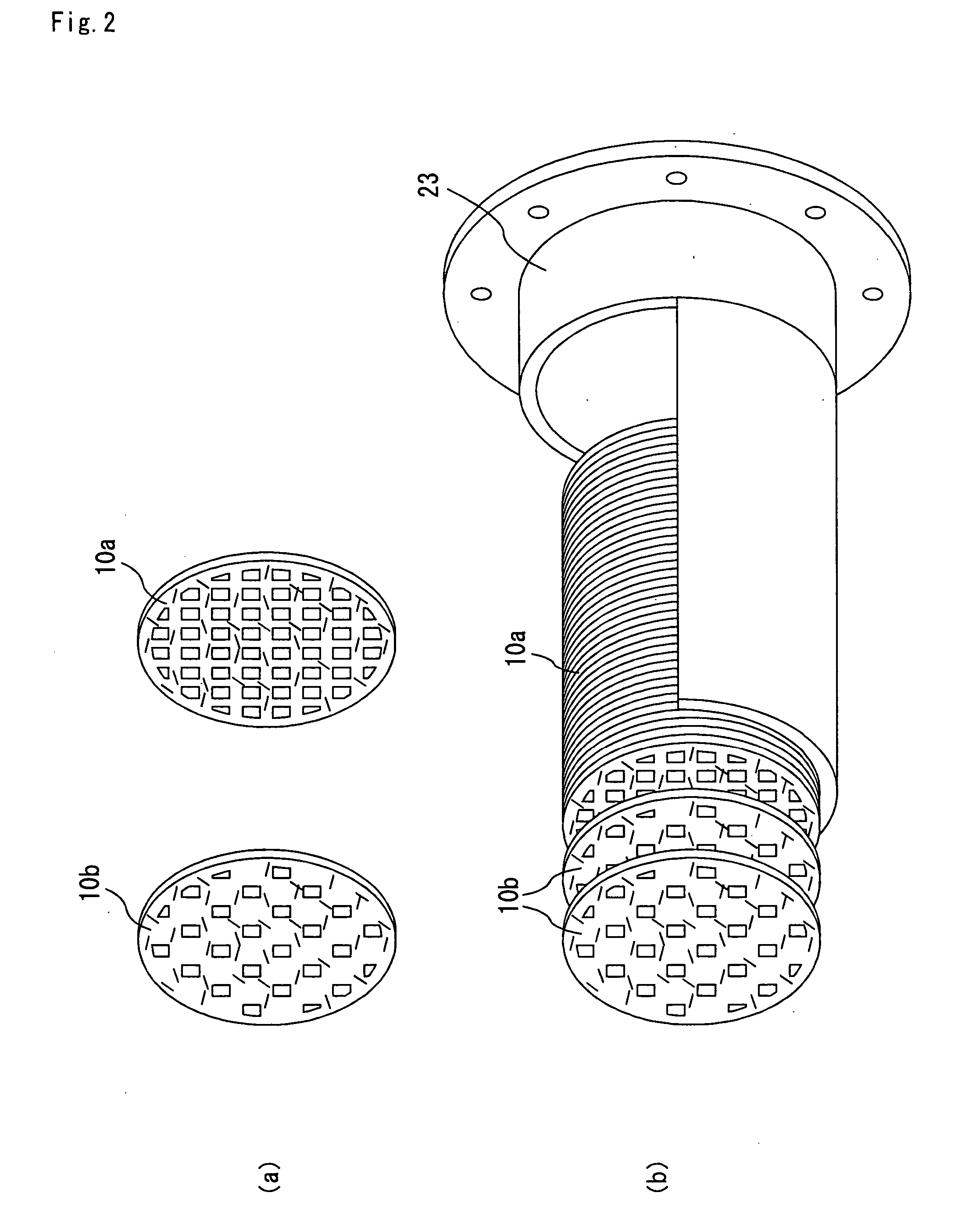
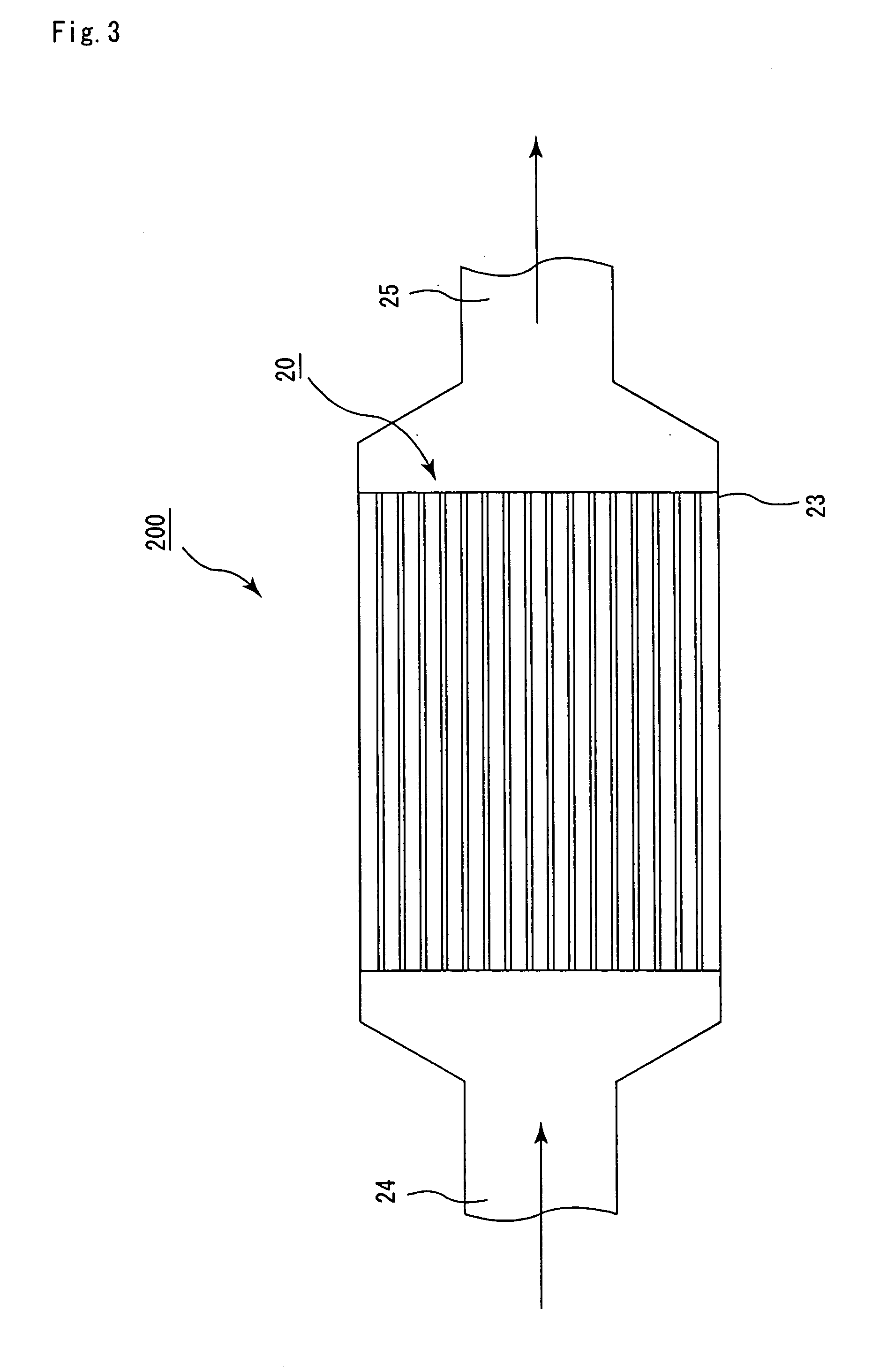
Honeycomb structural body
a technology of honeycomb and structural body, applied in the direction of catalyst activation/preparation, metal/metal-oxide/metal-hydroxide catalyst, etc., can solve the problems of high pressure loss, serious problems, and harmful particulates to the environment and the human body, so as to improve the purifying function, reduce the initial pressure loss, and increase the porosity
- Summary
- Abstract
- Description
- Claims
- Application Information
AI Technical Summary
Benefits of technology
Problems solved by technology
Method used
Image

Examples
example 1
(1) Process of Applying Catalyst to Inorganic Fibers
[0115] Alumina fibers (average fiber diameter: 5 μm, average fiber length: 0.3 mm) were impregnated with an alumina slurry bearing Pt (Pt concentration: 5 wt %) for two minutes, and then heated at 500° C. to prepare alumina fibers to which the catalyst is adhered. The amount of deposition of Pt was 0.24 g / 10 g of alumina.
(2) Process of Preparing Slurry for Paper-Making
[0116] Next, the inorganic fibers obtained from the process (1) were dispersed in water (1 L) at a rate of 10 g, and in addition to these, 5 wt % of silica sol serving as an inorganic binder and 3 wt % of an acrylic latex serving as an organic binder were added thereto. Further, a slight amount of aluminum sulfate serving as a coagulation agent and polyacrylic amid serving as an aggregation agent were further added thereto, and the mixture was sufficiently stirred to prepare a slurry for paper-making.
(3) Paper-Making Process
[0117] The slurry, obtained in the p...
examples 2 and 3
[0121] The same processes as Example 1 were carried out except that the amounts of deposition of Pt catalyst were changed to 0.1 g / 10 g of alumina (Example 2) and 0.15 g / 10 g of alumina (Example 3) to obtain honeycomb structural bodies. The amount of Pt deposition of the honeycomb structural body according to Example 2 was 2 g / l and the amount of Pt deposition of the honeycomb structural body according to Example 3 was 3 g / l.
examples 4 and 5
[0122] The same processes as Example 1 were carried out except that the fiber lengths of alumina fibers were changed to 10 mm (Example 4) and 50 mm (Example 5) to obtain honeycomb structural bodies.
PUM
| Property | Measurement | Unit |
|---|---|---|
| angle | aaaaa | aaaaa |
| angle | aaaaa | aaaaa |
| length | aaaaa | aaaaa |
Abstract
Description
Claims
Application Information