Switching power source apparatus and power factor corrector

a technology of power factor corrector and power source apparatus, which is applied in the direction of electric variable regulation, process and machine control, instruments, etc., can solve the problems of complex circuitry, high cost of photocoupler, and apparatus of fig. 1 that needs a signal transmitter, so as to reduce power consumption and simplify the structure

Active Publication Date: 2005-12-08
SANKEN ELECTRIC CO LTD
View PDF1 Cites 51 Cited by
  • Summary
  • Abstract
  • Description
  • Claims
  • Application Information

AI Technical Summary

Benefits of technology

[0015] According to the present invention, a switching power source apparatus and a power factor corrector, each having a simple structure, being inexpensive, and capable of reducing power consumption during a standby period are provided.

Problems solved by technology

In addition, the apparatus needs a signal transmitter such as a photocoupler that is expensive and involves the primary and secondary sides of a transformer that must be insulated from each other.
In this way, the apparatus of FIG. 1 is expensive and involves a complicated circuitry.
Namely, the tertiary winding does not provide a large voltage change with respect to a light-load state, and therefore, it is difficult for this disclosure to surely detect the light-load state.

Method used


Image

  • Switching power source apparatus and power factor corrector
  • Switching power source apparatus and power factor corrector
  • Switching power source apparatus and power factor corrector

Examples


first embodiment

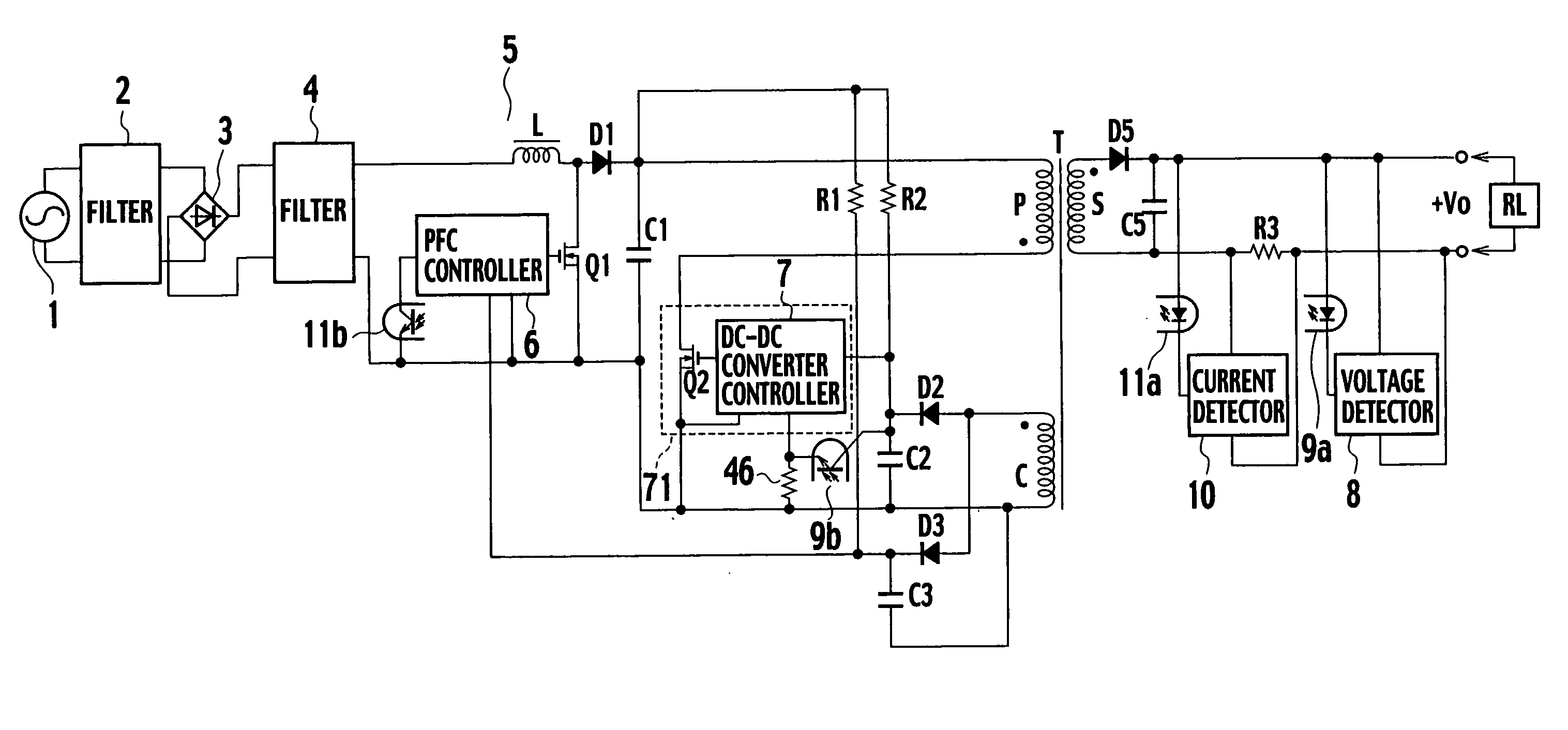
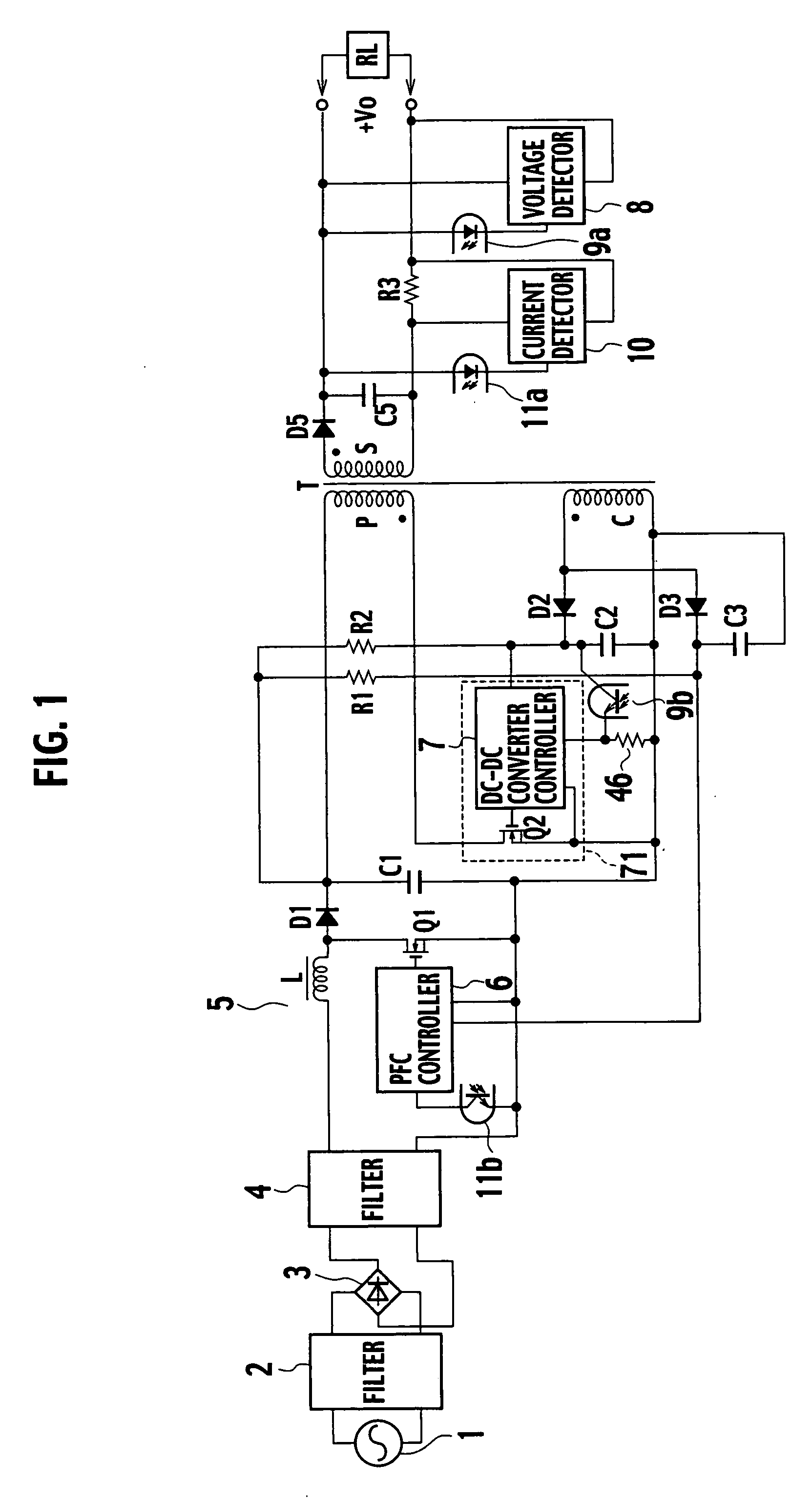
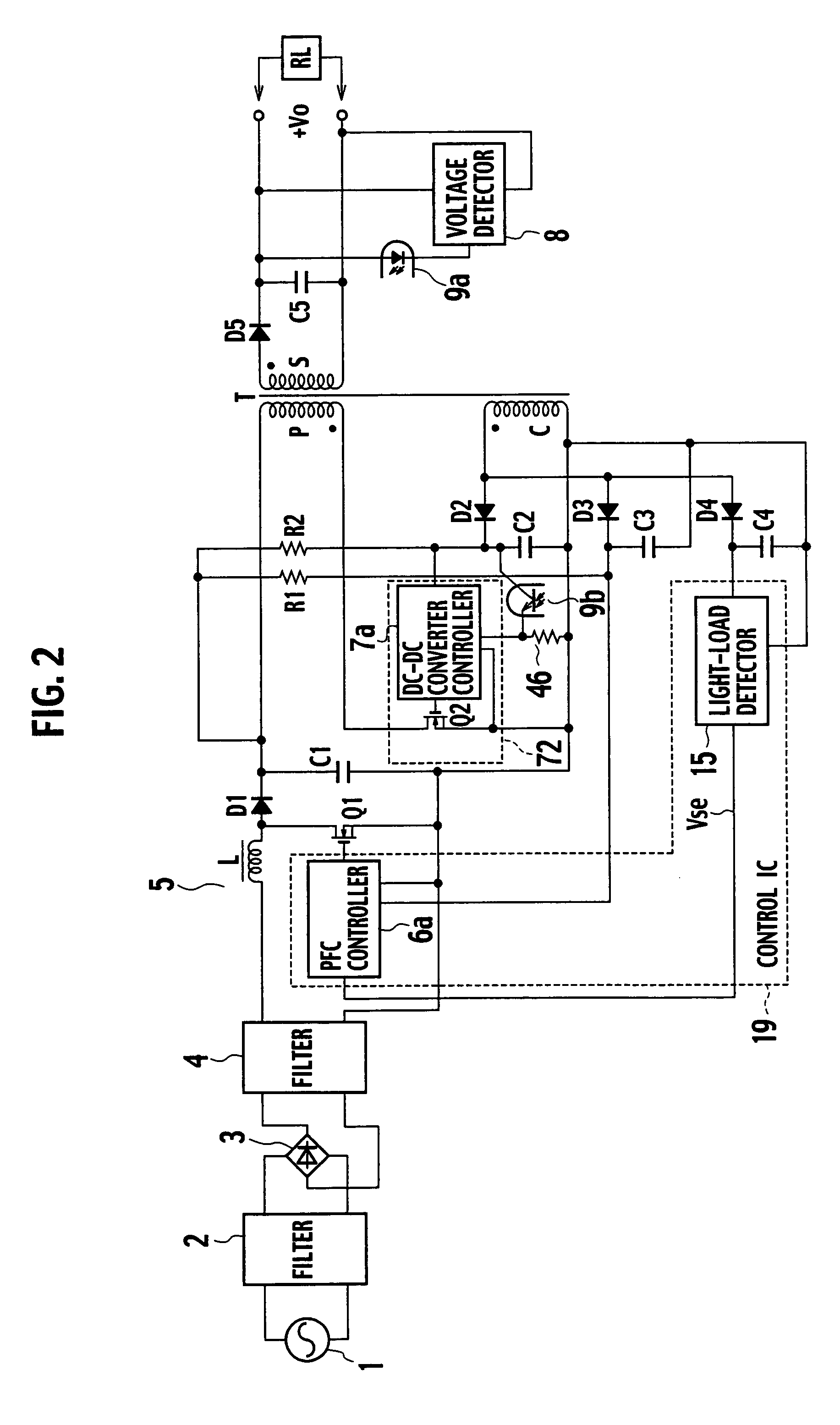
[0031]FIG. 2 is a circuit diagram showing a switching power source apparatus according to a first embodiment of the present invention. The apparatus of the first embodiment omits, from the switching power source apparatus of the related art shown in FIG. 1, the current detecting resistor R3 and current detector 10 on the secondary side of the transformer T and the light emitter 11a and photodetector 11b of the photocoupler. The apparatus of the first embodiment employs a diode D4, a smoothing capacitor C4, and a light-load detector 15.

[0032] An anode of the diode D4 is connected to a first end of a control winding C of a transformer T. A second end of the control winding C is connected to a first end of the smoothing capacitor C4. A second end of the smoothing capacitor C4 is connected to a cathode of the diode D4. The diode D4 and smoothing capacitor C4 form a second rectifying / smoothing circuit of the present invention. A diode D5 and a smoothing capacitor C5 form a first rectify...

second embodiment

[0055] A switching power source apparatus according to a second embodiment of the present invention will be explained with reference to FIG. 8.

[0056] In FIG. 8, a first end of a control winding C of a transformer T is connected to an anode of a diode D4. A cathode of the diode D4 is connected to a first end of a resistor R3. A second end of the resistor R3 is connected to a first end of a resistor R4 and a first end of a smoothing capacitor C4. A second end of the control winding C is connected to a second end of the smoothing capacitor C4 and a second end of the resistor R4. Each end of the smoothing capacitor C4 and each end of the resistor R4 are connected to a light-load detector 15.

[0057] The other parts of the second embodiment are the same as those of the first embodiment, and therefore, the same parts are represented with the same reference marks to omit the detailed explanation thereof.

[0058] The switching power source apparatus of the second embodiment shown in FIG. 8 d...


PUM


Abstract

A power factor corrector is connected to an AC power source, to provide a first DC voltage. A DC-DC converter supplies the first DC voltage from the power factor corrector to a primary winding of a transformer. A first rectifying / smoothing circuit rectifies and smoothes a voltage generated by a secondary winding of the transformer and supplies the rectified-and-smoothed voltage to a load. A second rectifying / smoothing circuit rectifies and smoothes a voltage generated by a control winding of the transformer. A light-load detector detects if an output ripple of the second rectifying / smoothing circuit is equal to or greater than a predetermined value, determines upon detection that the switching operation has decreased the frequency thereof or has shifted to an intermittent oscillation, and stops the power factor corrector.

Description

BACKGROUND OF THE INVENTION [0001] The present invention relates to a switching power source apparatus with a power factor corrector and a DC-DC converter and to a power factor corrector. In particular, the present invention relates to a technique to reduce power consumption during a standby period of such a switching power source apparatus. [0002]FIG. 1 shows a switching power source apparatus according to a related art. This apparatus has a power factor corrector (PFC) and a DC-DC converter connected to the PFC. The PFC conforms to input harmonic current regulations stipulated in IEC61000-3-2 recently established. [0003] Operation of the apparatus shown in FIG. 1 will be explained. An AC power source 1 provides a sinusoidal voltage, which is passed through a filter 2 and is full-wave-rectified with a diode bridge 3. The full-wave-rectified voltage is passed through a filter 4 and is supplied to the PFC 5. The full-wave-rectified voltage is passed through a reactor L, a diode D1 an...

Claims


Application Information

Patent Timeline
Patent Type & Authority Applications(United States)
IPC IPC(8): H02M7/12H02M1/42H02M3/28H02M3/335H02M5/42
CPCH02M1/4225H02M3/33523Y02B70/16H02M2001/007Y02B70/126H02M2001/0032Y02B70/10Y02P80/10H02M1/0032H02M1/007
Inventor USUI, HIROSHIOSAKA, SYOHEI
Owner SANKEN ELECTRIC CO LTD
Why Eureka
Try Eureka