Temperature sensor

a temperature sensor and sensor technology, applied in the field of temperature sensors, can solve the problems of inability to guarantee the accuracy of the ptap voltage, the loss the destruction of the semiconductor integrated circuit, so as to achieve the effect of improving the sensitivity and low-voltage operation

Inactive Publication Date: 2005-12-08
RICOH KK
View PDF25 Cites 17 Cited by
  • Summary
  • Abstract
  • Description
  • Claims
  • Application Information

AI Technical Summary

Benefits of technology

[0012] Therefore, it is an object of the present invention to provide a temperature sensor that is accurate even at a high operating temperature and has a flexibly selected temperature slope to improve the sensitivity or to allow a low-voltage operation.
[0019] With this structure, the temperature sensor makes use of the difference in gate work function to produce a PTAT voltage, and therefore, it is capable of stable operation even at a high temperature.
[0020] In addition, the temperature coefficient (or slope) of the PTAT voltage (that is, the first voltage) can be easily adjusted by simply adjusting the resistance values of the source follower.

Problems solved by technology

If an abnormally large quantity of electric current flows through a semiconductor integrated circuit, or if the temperature of the semiconductor integrated circuit rises too high due to the environmental change, the semiconductor integrated circuit will be destroyed.
In the latter case, the semiconductor integrated circuit will be destroyed.
However, there is a problem in the semiconductor temperature sensor shown in FIG. 1 that outputs the potential difference between the gate-source voltages Vgs of two MOS transistors.
The problem is that the temperature range for accurately extracting the PTAP voltage is limited to the range from −50° C. to 100° C. The accuracy of the PTAP voltage cannot be guaranteed at a higher temperature above 100° C., at which the semiconductor integrated circuit is very likely to be destroyed.
The circuit shown in FIG. 2 using a diode connection is also disadvantageous because the PTAP voltage is adversely affected by process variation, and is incapable of outputting a precise PTAT voltage.
In addition, the slope of the PTAT voltage in proportion to the absolute temperature (i.e., the temperature slope) cannot be adjusted freely because the temperature slope is fixed by the process.
The structure shown in FIG. 2 is lacking in flexibility for designing different types of circuits, such as a highly precise temperature sensing circuit with a large temperature slope, or a low-voltage operating circuit with a small temperature slope.
Another problem in the prior art techniques is difficulty in producing a constant and stable reference voltage, with which the detected PTAT voltage is compared, independently of the temperature.

Method used


Image

  • Temperature sensor
  • Temperature sensor
  • Temperature sensor

Examples


first embodiment

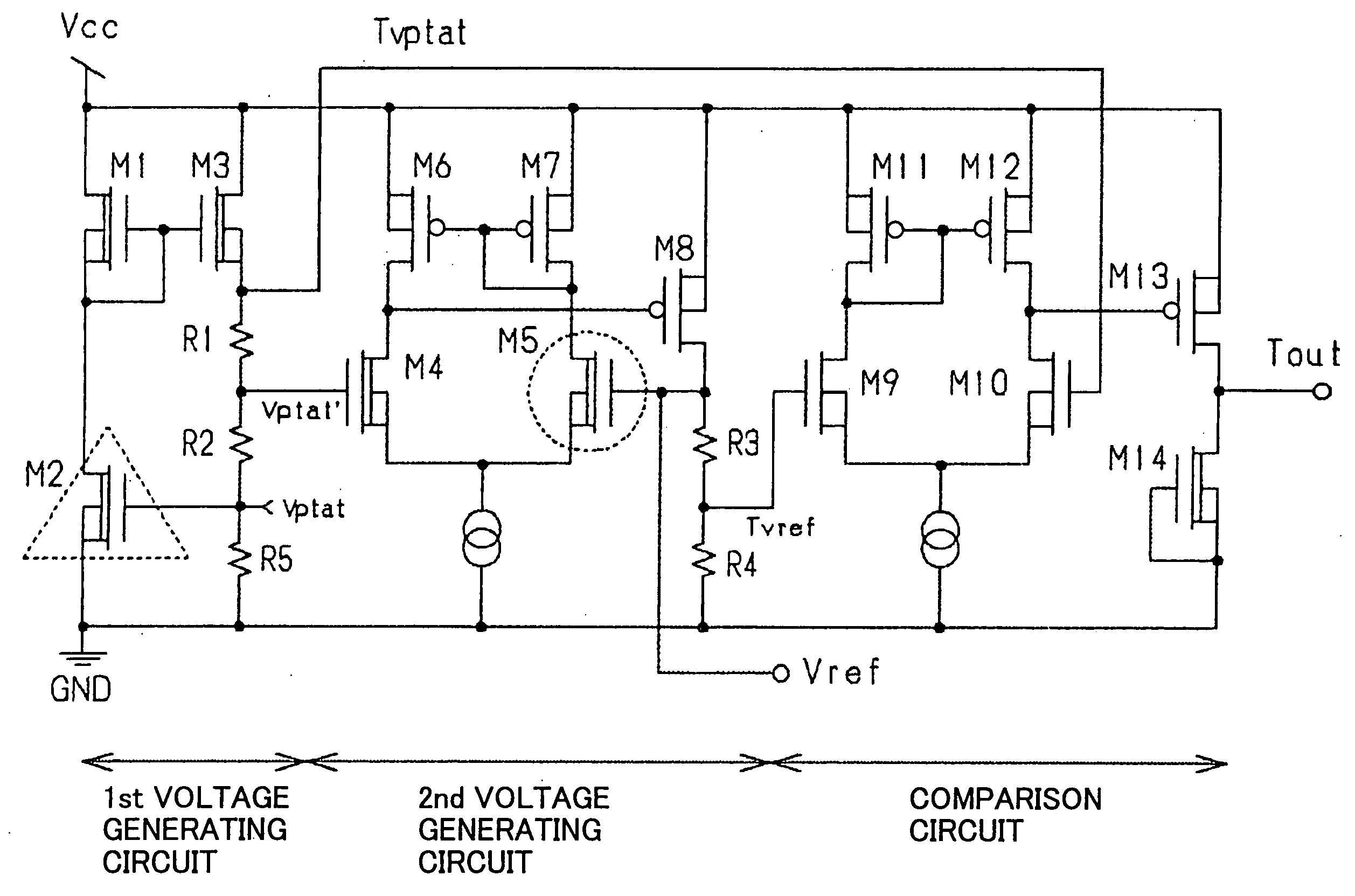
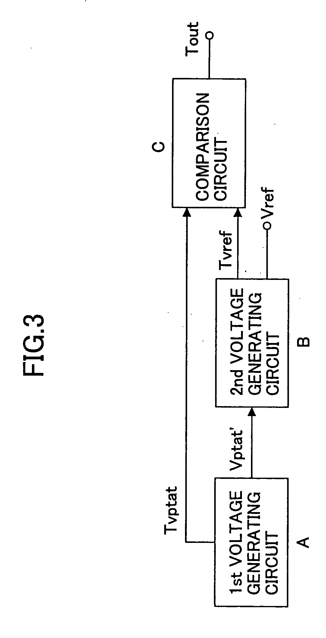
[0057]FIG. 3 is a block diagram of the temperature sensor according to the first embodiment of the invention. The temperature sensor comprises a first voltage generating circuit A, a second voltage generating circuit B, and a comparison circuit C. The first voltage source A outputs a PTAT voltage (referred to as “Tvptat” in the first embodiment), which has a positive temperature coefficient in proportion to the absolute temperature, as well as a voltage Vptat′, which also has a positive temperature coefficient and is obtained from Tvptat through a voltage-divider. Tvptat is supplied to the comparison circuit for the comparison with the reference voltage. On the other hand, Vptat′ is supplied to the second voltage generating circuit for obtaining a reference voltage.

[0058] The second voltage generating circuit B generates a voltage having a negative temperature coefficient, and adds this voltage to Vptat′ supplied from the first voltage generating circuit A to output a first referen...

second embodiment

[0103]FIG. 12 is a block diagram of the temperature sensor according to the second embodiment. The temperature sensor comprises a first voltage generating circuit, a second voltage generating circuit, a subtraction circuit, and a comparison circuit. In the second embodiment, the output of the subtraction circuit is compared with the reference voltage. This arrangement is capable of reducing the operating voltage, while maintaining high sensitivity.

[0104] The first voltage generating circuit generates a voltage Svptat in proportion to the absolute temperature. Svptat has either a positive or negative temperature coefficient. This Svptat is supplied to the subtraction circuit. The second voltage generating circuit generates a first reference voltage Vref, a second reference voltage Tvref, and a third reference voltage Svref, none of which has a temperature coefficient. While the second reference voltage Tvref is supplied to the comparison circuit, the third reference voltage Svref is...

third embodiment

[0148]FIG. 17 is a block diagram of the temperature sensor according to the third embodiment of the invention. The temperature sensor comprises a first voltage generating circuit, a second voltage generating circuit, a subtraction circuit, and a comparison circuit, as in the second embodiment. In the third embodiment, a voltage Vptat′ is output from the first voltage generating circuit, and supplied to the second voltage generating circuit. This Vptat′ is used in the second generating voltage circuit to produce a reference voltage.

[0149] The first voltage generating circuit also outputs Svptat, in adiition to Vptat′. The Svptat and Vptat′ are produced from a PTAT voltage (not shown in FIG. 17) originally generated in the first voltage generating circuit in proportion to the absolute temperature, through voltage conversion at predetermined ratios using a voltage divider. In the second embodiment, the PTAT voltage, Svptat, and Vptat′ have positive temperature coefficients.

[0150] The...


PUM

PropertyMeasurementUnit
temperatureaaaaaaaaaa
voltageaaaaaaaaaa

Abstract

A temperature sensor comprises (a) a first voltage generating circuit that generates and outputs a first voltage having a positive or negative temperature coefficient in proportion to the absolute temperature; (b) a second voltage generating circuit that generates a second voltage having an opposite sign of temperature coefficient compared to the first voltage and outputs a reference voltage that does not have a temperature coefficient based on the second voltage; and (c) a comparator that compares the first voltage output from the first voltage generating circuit with the reference voltage output from the second voltage generating circuit.

Description

BACKGROUND OF THE INVENTION [0001] 1. Field of the Invention [0002] The present invention generally relates to a temperature sensor, and more particularly, to a temperature sensor for detecting the operating temperature of, for example, an LIS or other semiconductor devices, which is capable of stable operation in a high temperature range, while realizing at least one of a highly sensitive operating mode and a low-voltage operating mode. [0003] 2. Description of the Related Art [0004] If an abnormally large quantity of electric current flows through a semiconductor integrated circuit, or if the temperature of the semiconductor integrated circuit rises too high due to the environmental change, the semiconductor integrated circuit will be destroyed. To prevent the destruction, the operation of the semiconductor integrated circuit has to be stopped before the detected temperature reaches the critical temperature. To this end, a temperature sensor or a temperature protection circuit is ...

Claims


Application Information

Patent Timeline
Patent Type & Authority Applications(United States)
IPC IPC(8): G01K7/01
CPCG01K7/01
Inventor AOTA, HIDEYUKIWATANABE, HIROFUMI
Owner RICOH KK
Why Eureka
Try Eureka