Antenna Amplifier, in particular for a magnetic resonance antenna

an amplifier and magnetic resonance technology, applied in the field of magnetic resonance antennas, can solve problems such as seriousness at higher frequencies, and achieve the effect of suppressing sheath waves

Active Publication Date: 2005-12-08
SIEMENS HEALTHCARE GMBH
View PDF4 Cites 13 Cited by
  • Summary
  • Abstract
  • Description
  • Claims
  • Application Information

AI Technical Summary

Benefits of technology

[0006] An object of the present invention is to suppress she

Problems solved by technology

Since the problem is thus for the most part of a capac

Method used


Image

  • Antenna Amplifier, in particular for a magnetic resonance antenna
  • Antenna Amplifier, in particular for a magnetic resonance antenna
  • Antenna Amplifier, in particular for a magnetic resonance antenna

Examples


Embodiment Construction

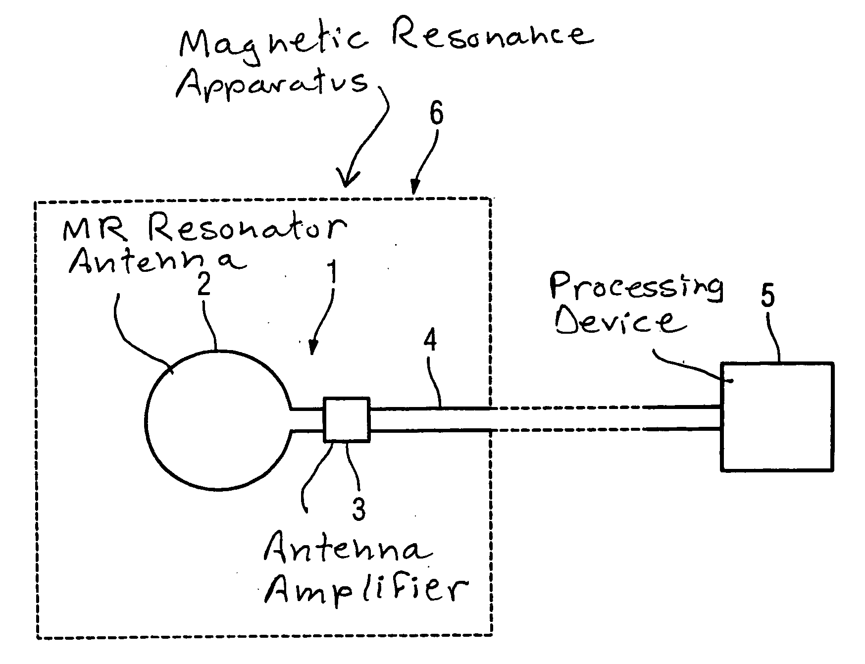
[0024]FIG. 1 shows an inventive magnetic resonance antenna 1 (also called a “loop antenna”) composed of a resonator 2 forming a surface coil as well as a downstream antenna amplifier 3 that serves for amplification of the acquired signal, that is output to a control and processing device 5 via a coaxial signal line 4. In the typical operating case, the MR antenna 1 is located within a magnetic resonance apparatus 6 that here is indicated only schematically.

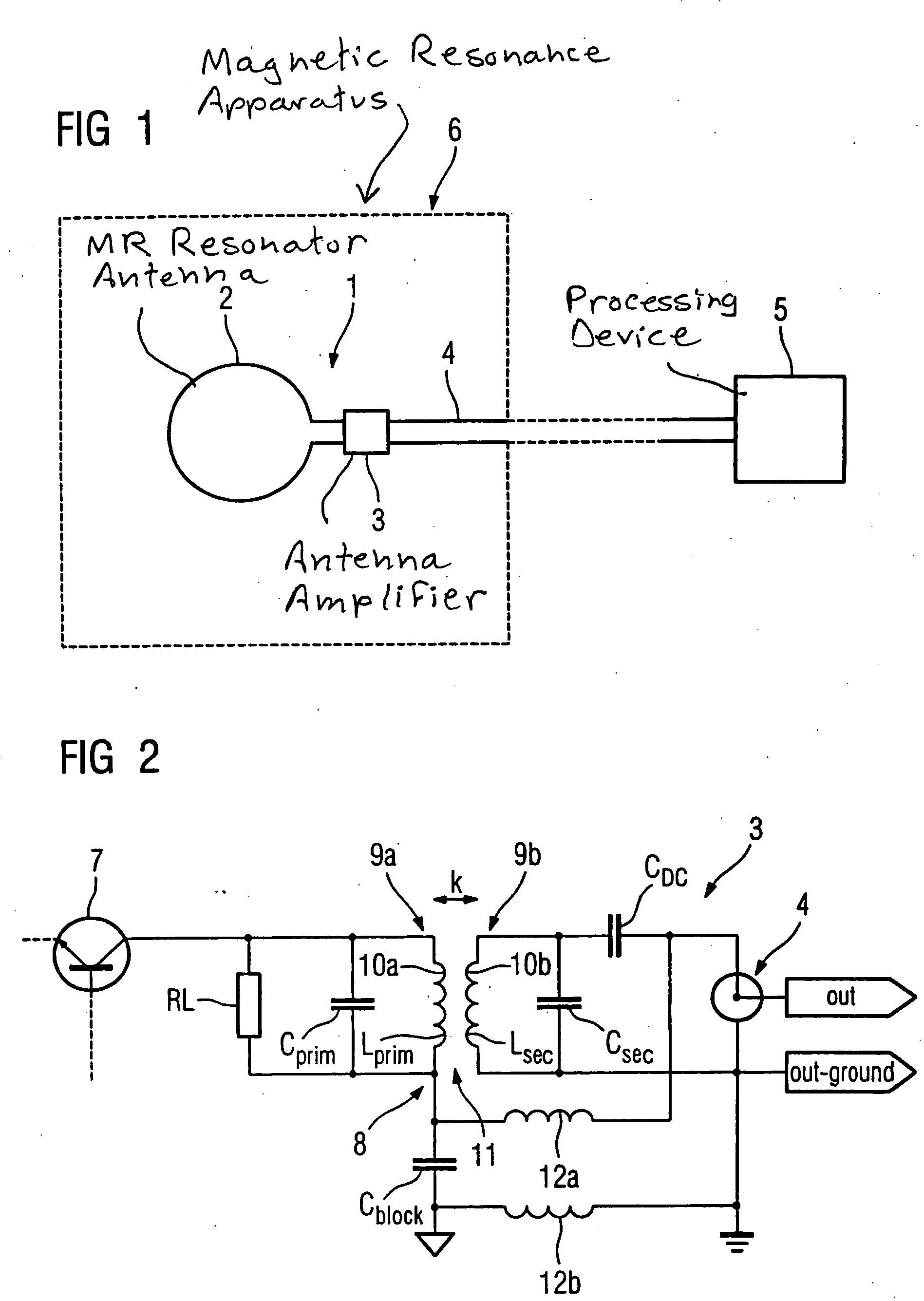
[0025] A sheath wave barrier is inventively integrated into the antenna amplifier 3 for suppression of sheath wave currents that form at the coaxial signal cable 4. FIG. 2 shows a first exemplary embodiment.

[0026] The antenna amplifier 3 is shown in sections with its collector output circuit that has been formed into a sheath wave barrier. An amplifier element 7 is shown in form of a bipolar transistor together with a load resistor RL (for example in the range of 1 kΩ) that is transformed via a two-storage band filter 8 (formed ...


PUM


Abstract

An antenna amplifier, in particular for a magnetic resonance antenna, has a sheath wave barrier integrated into the signal path of the antenna amplifier in the form of a component designed exclusively for transfer of a differential signal.

Description

BACKGROUND OF THE INVENTION [0001] 1. Field of the Invention [0002] The invention concerns an antenna amplifier, in particular for a magnetic resonance antenna. [0003] 2. Description of the Prior Art [0004] In magnetic resonance technology, local surface coils (known as “loop antennas”) or array arrangements assembled from local coils are used for acquisition of image information of the examination subject. Such surface coils or antennas include the actual antenna or receiver component (resonator), the signals from which are supplied to an antenna amplifier that is disposed relatively close to the reception component. There the (possibly noise-afflicted) signal is amplified and conducted from the MR apparatus via a coaxial line for further processing. Sheath currents or the sheath waves as a consequence thereof that are created in the region of the coaxial line cause problems. These generate E-fields and B-fields that form between the “transparent” coaxial line and the surroundings....

Claims


Application Information

Patent Timeline
IPC IPC(8): G01R33/36G01V3/00
CPCG01R33/3614
Inventor OPPELT, RALPHVESTER, MARKUS
Owner SIEMENS HEALTHCARE GMBH
Why Eureka
Try Eureka