Integrated high efficiency fossil fuel power plant/fuel cell system with CO2 emissions abatement

a high-efficiency, fuel cell technology, applied in the direction of electrochemical generators, fuel cells for electrolyte, emergency supply, etc., can solve the problems of complex and expensive system, unfavorable environment, and ineffective process of separating carbon dioxide from flue gas

Active Publication Date: 2005-12-08
FUELCELL ENERGY INC
View PDF5 Cites 125 Cited by
  • Summary
  • Abstract
  • Description
  • Claims
  • Application Information

AI Technical Summary

Benefits of technology

[0010] In one form of further processing, the anode exhaust gas is processed to sequester or segregate the carbon dioxide gas and then dispose of the sequestered gas. In another form of this processing, the anode exhaust gas is carried to a carbon dioxide tolerant low temperature fuel cell for use as fuel. In yet another form of processing, the anode exhaust gas is passed through a carbon

Problems solved by technology

Such emissions, however, are harmful to the environment because they contain large amounts of carbon dioxide which contributes to global warming and climate changes.
However, the process of separating the carbon dioxide from the flue gas is not

Method used


Image

  • Integrated high efficiency fossil fuel power plant/fuel cell system with CO2 emissions abatement
  • Integrated high efficiency fossil fuel power plant/fuel cell system with CO2 emissions abatement
  • Integrated high efficiency fossil fuel power plant/fuel cell system with CO2 emissions abatement

Examples


example 1

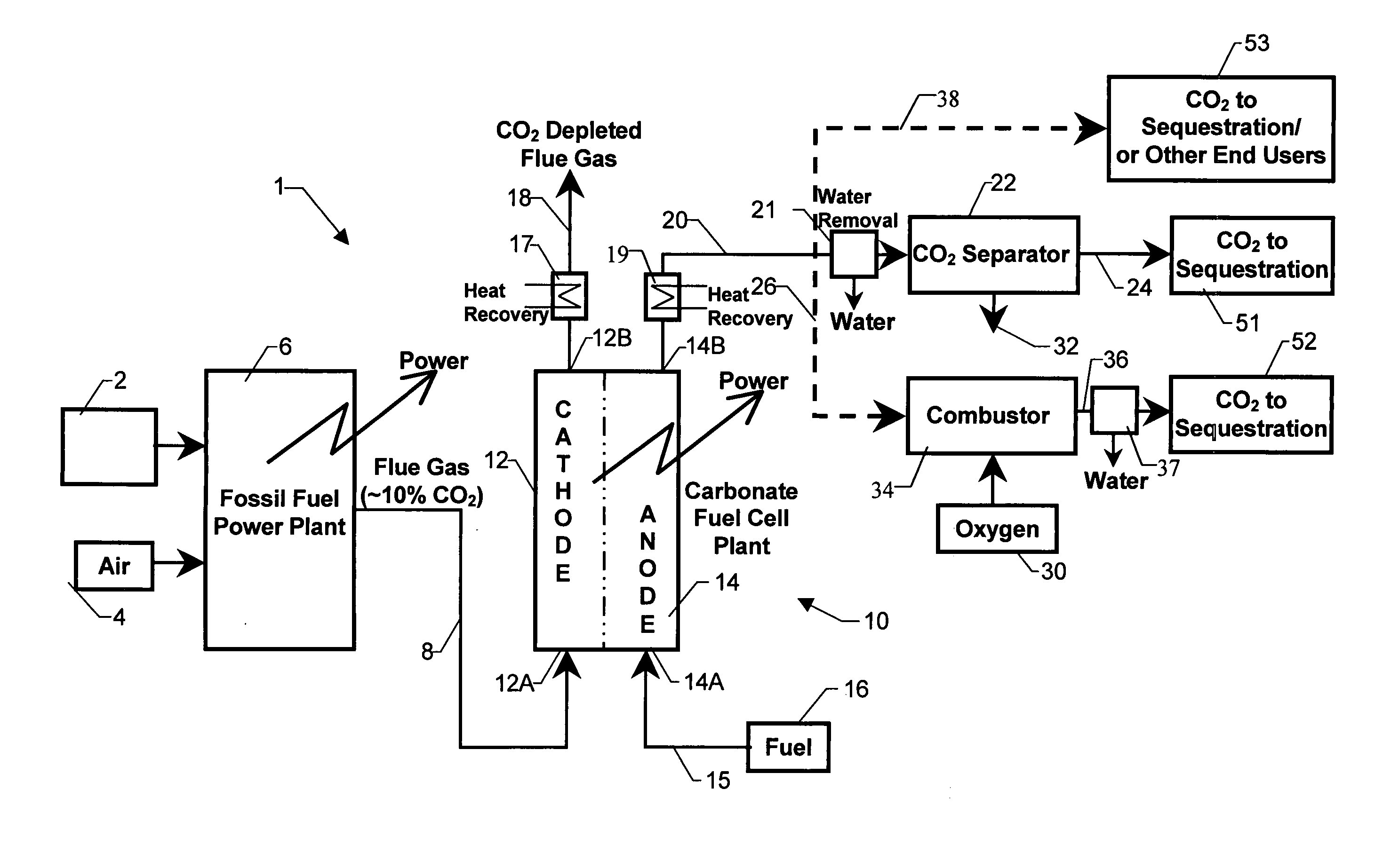
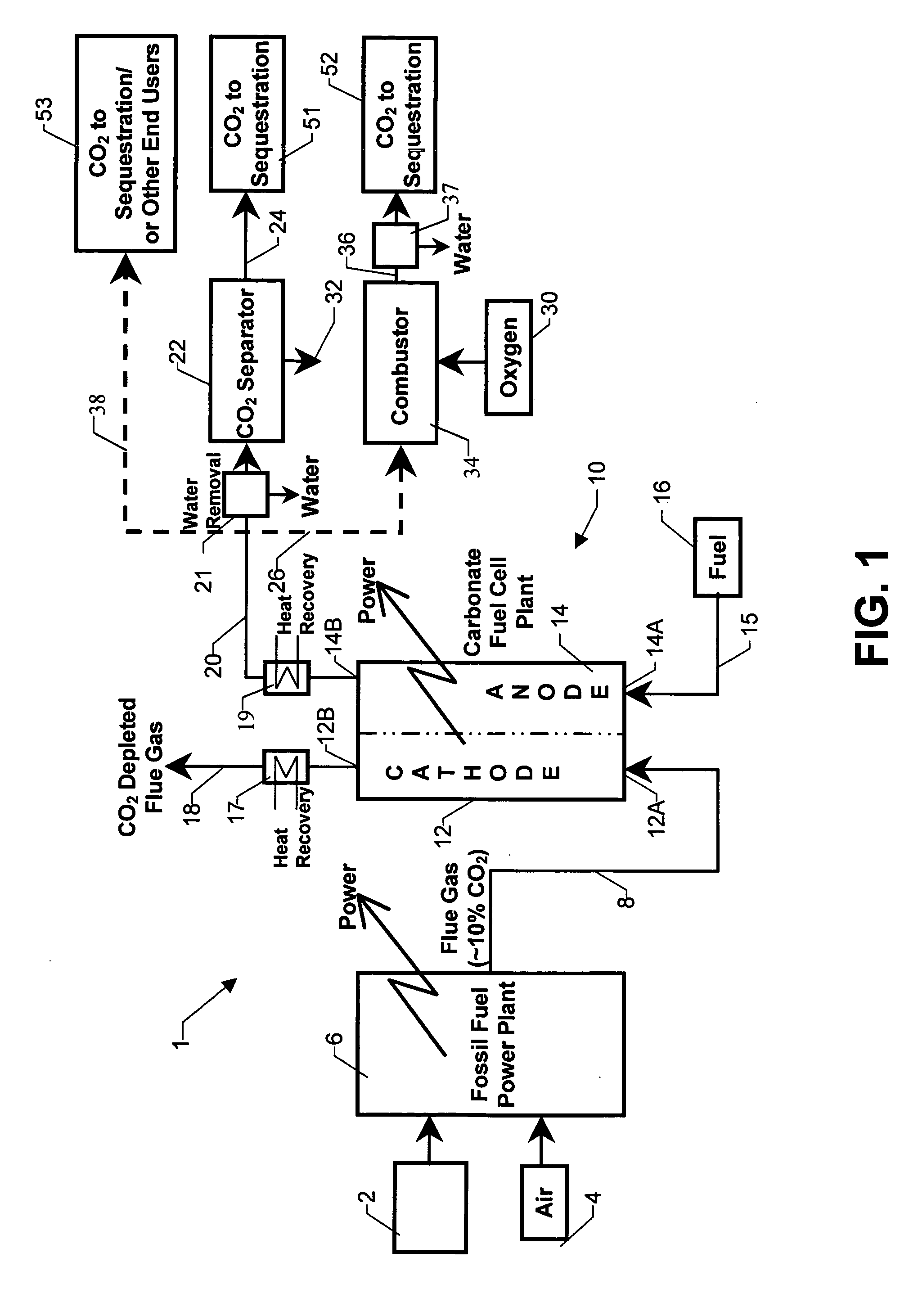
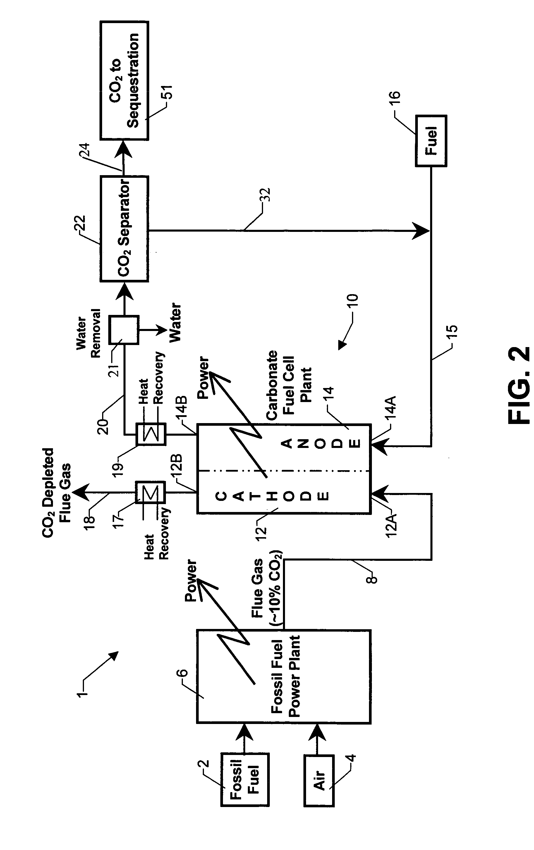
[0030] In this example, the system 1 was configured to combine a coal processing power plant 6 in a tandem arrangement with a molten carbonate fuel cell 10 as shown in FIG. 2. Natural gas is delivered to the fuel cell anode 14 from the fuel supply 16. In this arrangement, the coal processing power plant 6 is a conventional combustion turbine adapted to run on gasified coal and produces approximately 70% of the total power produced by the system 1, while the fuel cell 10 produces approximately 30% of the total power.

[0031] The system 1 in this example is provided with a carbon dioxide recovery assembly comprising a carbon dioxide separator 22 as shown in FIG. 2. In addition, after the removal of carbon dioxide in the carbon dioxide separator 22, anode exhaust gas is recycled back to the anode inlet 14A. Although not shown, a small portion of the exhaust gas from separator 22 can be vented out side to prevent accumulation of inert gases such as nitrogen in the fuel stream.

[0032] In ...

example 2

[0035] In this example, the system 1 comprises a conventional natural gas power plant 6 arranged in tandem with a molten carbonate fuel cell 10 operating on natural gas. The natural gas power plant 6 in this example comprises a conventional combustion turbine which combusts natural gas to produce power. Carbon dioxide in the anode exhaust gas produced by this system 1 is transferred out of the system 1 and sequestered as shown in FIG. 2. Although not shown in the figure, a portion of the CO2 separated from the anode gas is sent to the cathode inlet to maintain the required CO2 concentrations for efficient fuel cell operation. The remainder of the CO2 is sequestered. The system configuration in this example again achieves approximately 65% reduction in carbon dioxide emissions and achieves a very low emissions level of 0.27 lbs of CO2 / kwh.

[0036] A system analysis was carried out on the integrated system described in this example and compared with the system analyses for a convention...


PUM


Abstract

An integrated power production system including a fossil fuel power plant for processing fossil based fuel such as coal or natural gas arranged in tandem with a carbonate fuel cell having an anode and a cathode section. The flue gas of the power plant serves exclusively as the inlet gas for the cathode section of the fuel cell. Anode exhaust gas leaving the anode section of the fuel cell is subjected to processing including sequestration of the carbon dioxide in the exhaust gas.

Description

BACKGROUND OF THE INVENTION [0001] This invention relates to fuel cell systems and, in particular, to integrated fuel cell and fossil fuel power plant systems having enhanced efficiency. [0002] A fuel cell is a device which directly converts chemical energy stored in hydrocarbon fuel into electrical energy by means of an electrochemical reaction. Generally, a fuel cell comprises an anode and a cathode separated by an electrolyte, which serves to conduct electrically charged ions. Molten carbonate fuel cells operate by passing a reactant fuel gas through the anode, while oxidizing gas comprising carbon dioxide and oxygen is passed through the cathode. [0003] Fossil fuel power plants produce energy by combusting fossil fuels, such as coal or natural gas. As a result of the combustion process, fossil fuel power plants generate flue gas, which is often disposed of by atmospheric emissions. Such emissions, however, are harmful to the environment because they contain large amounts of carb...

Claims


Application Information

Patent Timeline
IPC IPC(8): H01M8/04H01M8/06H01M8/14
CPCH01M8/04014H01M8/04111H01M8/04156H01M8/0612H01M8/0637H01M8/0662H01M8/0668H01M2008/147H01M2250/10H01M2250/402Y02B90/12Y02B90/14Y02E60/526Y02E60/566Y02B90/10Y02E60/50H01M8/04H01M8/06H01M8/14
Inventor FAROOQUE, MOHAMMADJAHNKE, FRED C.
Owner FUELCELL ENERGY INC
Why Eureka
Try Eureka