

Method of forming nanocomposite materials
- Summary
- Abstract
- Description
- Claims
- Application Information
AI Technical Summary
Problems solved by technology
Method used
Image

Examples
example 1
[0032] Samples of spherical silica epoxy nanocomposites and layered silicate epoxy nanocomposites were formed using the method of the present invention in which sphered silica nanoparticles or nanosheets of layered silicate were combined with acetone followed by the addition of an epoxy resin (Epon 862 or Epon 828 from Shell), a curing agent (Jeffamine® from Huntsman Chemical) with or without a coupling agent (3-glycidoxypropyltrimethoxy silane or 3-aminopropyltrimethoxy silane).
[0033] The introduction of nanosize spherical silica into the epoxy resin resulted in good dispersion without significant precipitation.
[0034] The dispersion of the nanosheets in the epoxy resin matrix was relatively good. Despite these initial conclusions, additional testing has shown that the spherical silica particles were aggregated, and the silicate nanosheets were stacked together. The layered silicates are intercalated nanocomposites or a mixture of intercalated and partially exfoliated nanocomposit...
example 2
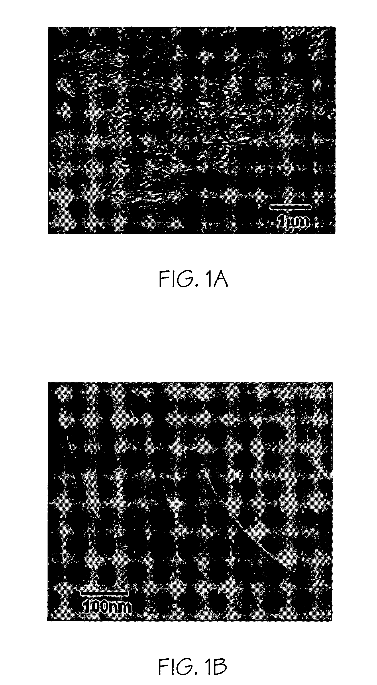
[0036] A nanocomposite was made with 1.5% organoclay (SC18), epoxy resin (Epon 862), and a curing agent (curing agent W (diethyltoluenediamine)) using the stir-bar method. The x-ray diffraction of the cured nanocomposite shows that the interplanar spacing is more than 100 Å. Although an exfoliated nanostructure is often assumed in most literature when x-ray diffraction cannot detect the (001) peak of the epoxy nanocomposite (mostly beyond about 80 Å), we have found that they are not strictly exfoliated at all. The TEM image of FIG. 1 shows that the silicate nanosheets are stacked together. The size for the aggregation is from 1 to teen μm. The interplanar spacing is from about 100 to about 200 Å.
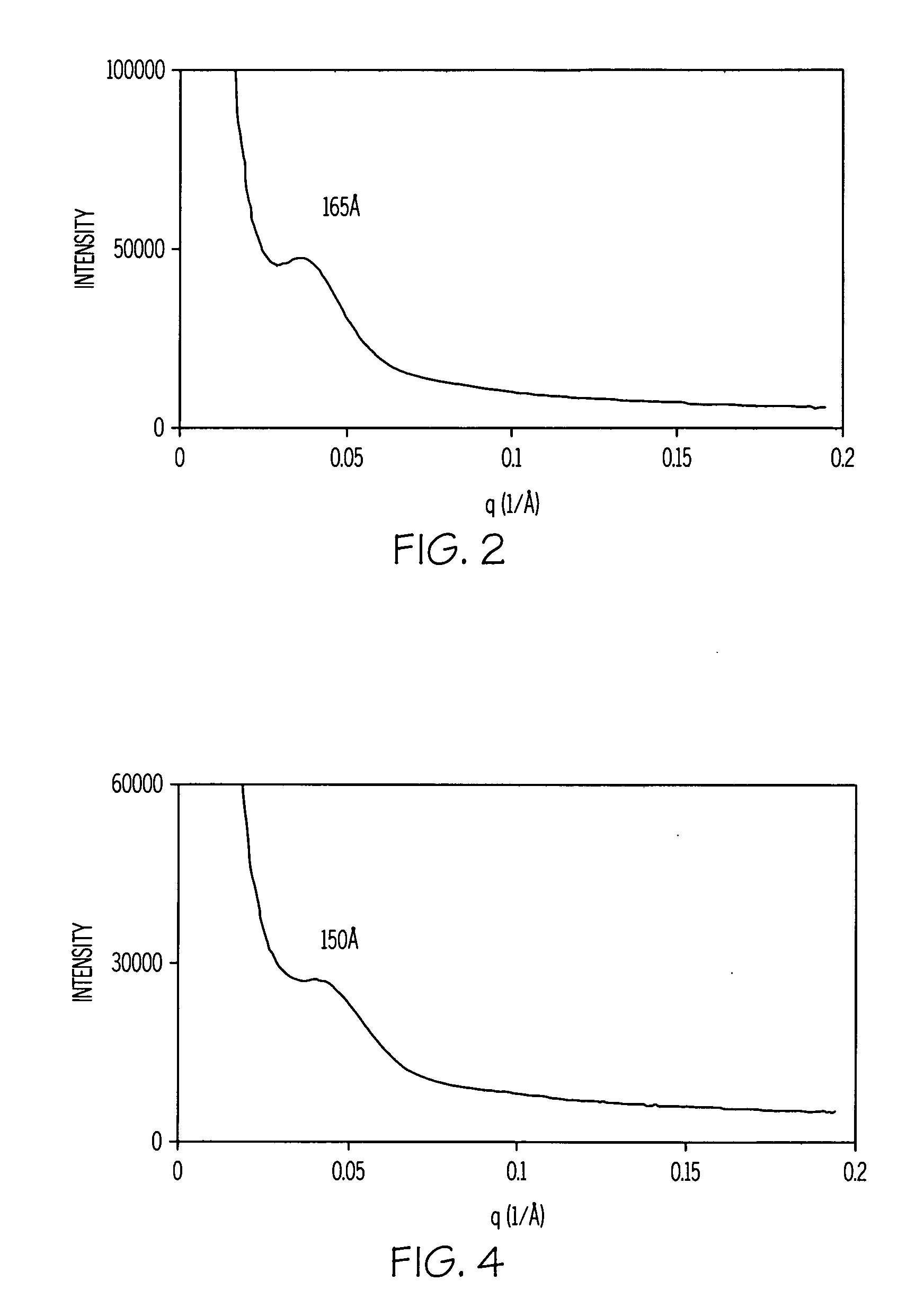
[0037] The small-angle x-ray scattering was used to characterize the morphologies of the nanocomposites further. The small-angle x-ray scattering (SAXS) of this nanocomposite is shown in FIG. 2. SAXS data indicated that the interplanar spacing is about 165 Å in the ordered structure of the ...
example 3
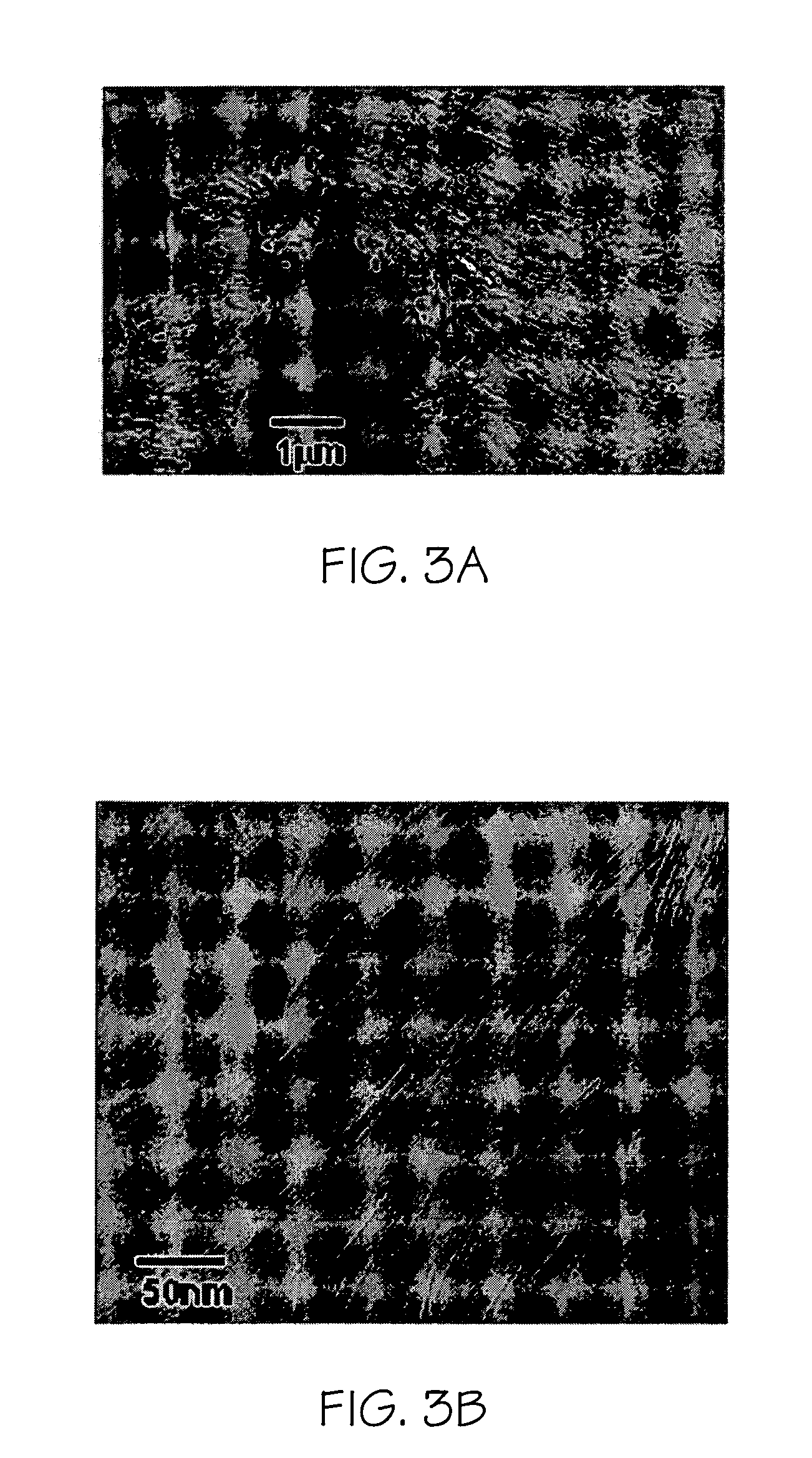
[0038] A nanocomposite was made with 2.5% organoclay (SC8), epoxy resin (Epon 862), and a curing agent (curing agent W). The TEM image is shown in FIG. 3. The particle size is very large. Some particles can be as large as teen μm. The TEM image at high magnification shows that the interplanar spacings in the gallery of the clay nanosheets is typically from 15 to 20 nm. The small-angle x-ray scattering of this nanocomposite is shown in FIG. 4. SAXS data indicated that the interplanar spacing of this nanocomposite is about 150 Å. The gallery of the organoclay was expanded significantly as compared to the original interplanar spacing of 13.4 Å of organoclay SC8. It is an intercalated nanocomposite with very large interplanar spacing (150 Å).
[0039] The high-shear mixing method of the present invention was also evaluated. In this method, the organoclay was dispersed in a solvent (acetone) using a high-shear mixer in a sonication bath for about 3 to 6 hours. The epoxy resin and acetone m...
PUM
| Property | Measurement | Unit |
|---|---|---|
| Thermoplasticity | aaaaa | aaaaa |
| Morphology | aaaaa | aaaaa |
| Evaporation enthalpy | aaaaa | aaaaa |
Abstract
Description
Claims
Application Information