Solar cells having a transparent composition-graded buffer layer

a technology of composition and buffer layer, which is applied in the field of solar cells having a composition graded buffer layer, can solve the problems of degradation the requirement of nearly perfect lattice matching, and the deterioration of the overall efficiency of the solar cell, so as to improve the performance improve the efficiency of the individual subcell, and reduce internal stresses and strains.

Active Publication Date: 2005-12-15
THE BOEING CO
View PDF11 Cites 122 Cited by
  • Summary
  • Abstract
  • Description
  • Claims
  • Application Information

AI Technical Summary

Benefits of technology

[0016] The present invention provides an improved solar (photovoltaic) cell that is most preferably utilized as a multifunction structure. The solar cell offers increased efficiency and performance, with little change in cost, as compared with conventional solar cells.
[0020] The use of the graded buffer layer achieves the desired lattice matching and epitaxial relationship through the thickness of the solar cell. This lattice matching and epitaxial relationship is needed to minimize internal stresses and strains, and for good electron movement through the thickness of the solar cell. The graded buffer layer also allows the requirement for lattice matching of the photoactive layers to be relaxed, so that their compositions may be chosen to produce the optimal bandgaps for photoconversion of the incident portions of the solar spectrum. The result is improved performance of the individual subcells, and improved performance of the solar cell.

Problems solved by technology

A limitation in the existing 4J, 5J, and 6J devices (and cells with even more junctions) is the requirement of nearly perfect lattice matching of the inserted subcell and the underlying and overlying materials.
Any substantial deviation, such as more than about + / −0.1 percent difference, in lattice parameter without proper design to incorporate the change in lattice parameter will result in degradation of the overall efficiency of the solar cell.
Another limitation is the reliance on the GaInAsN alloy lattice-matched to the GaAs or Ge layers.
The lattice-matched GaInAsN material has poor quality when produced by available techniques.
The problem results from the need to incorporate a large amount of nitrogen to achieve the 1.0 eV band gap and the lattice-matched condition simultaneously.

Method used


Image

  • Solar cells having a transparent composition-graded buffer layer
  • Solar cells having a transparent composition-graded buffer layer
  • Solar cells having a transparent composition-graded buffer layer

Examples


Embodiment Construction

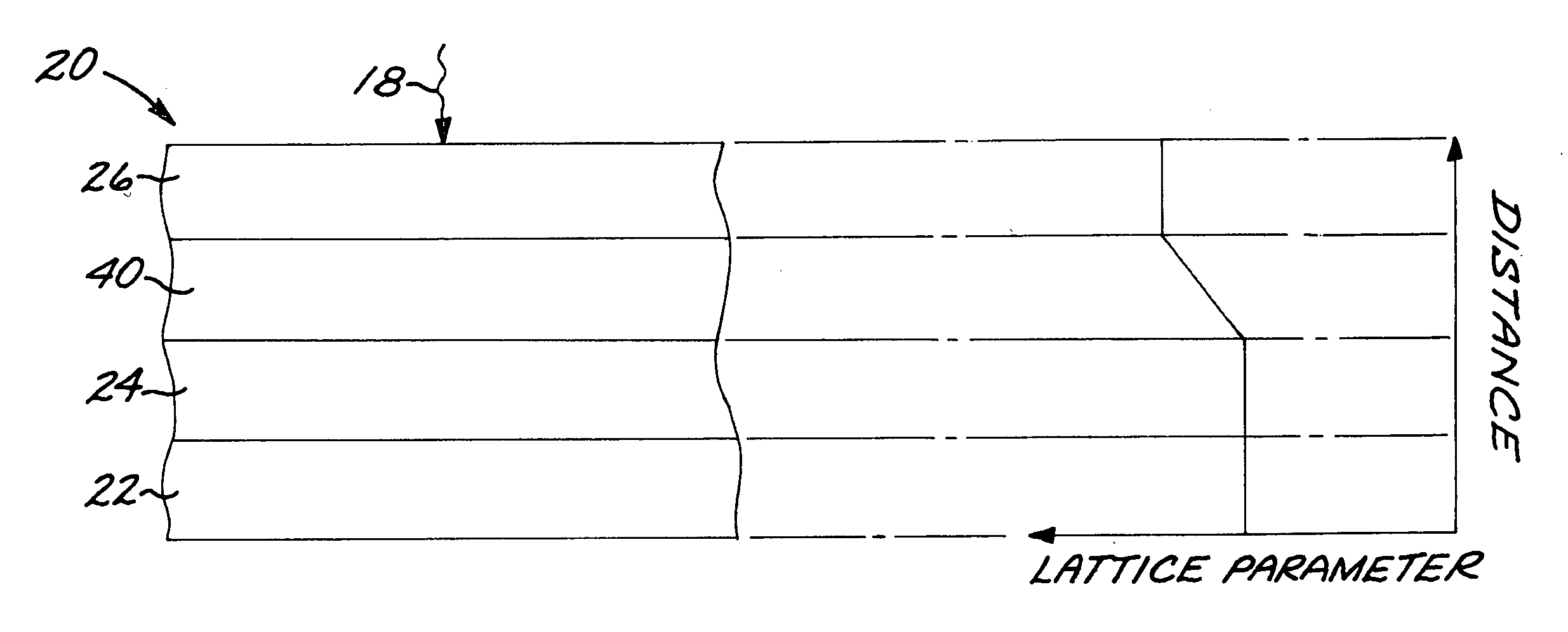
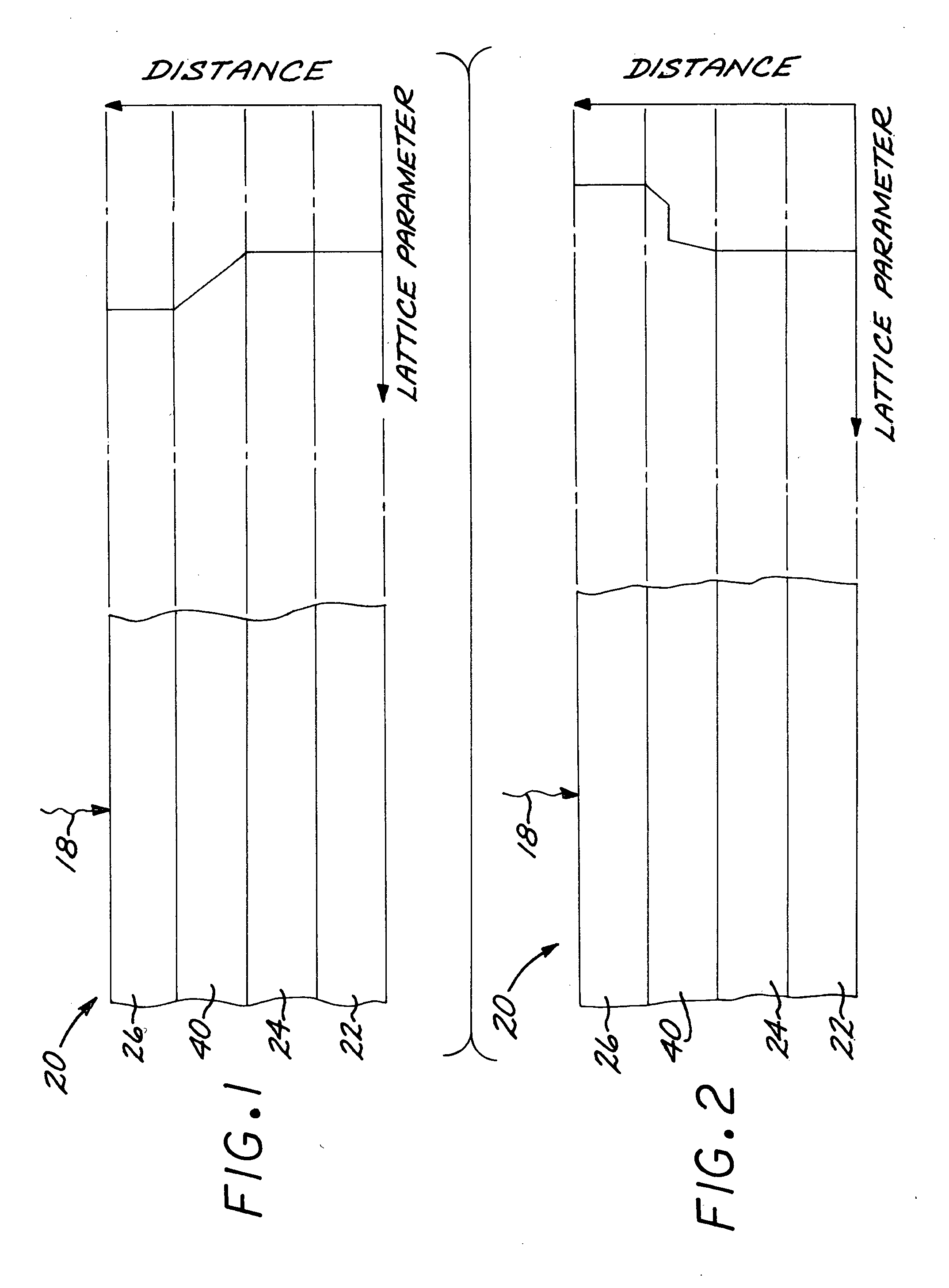
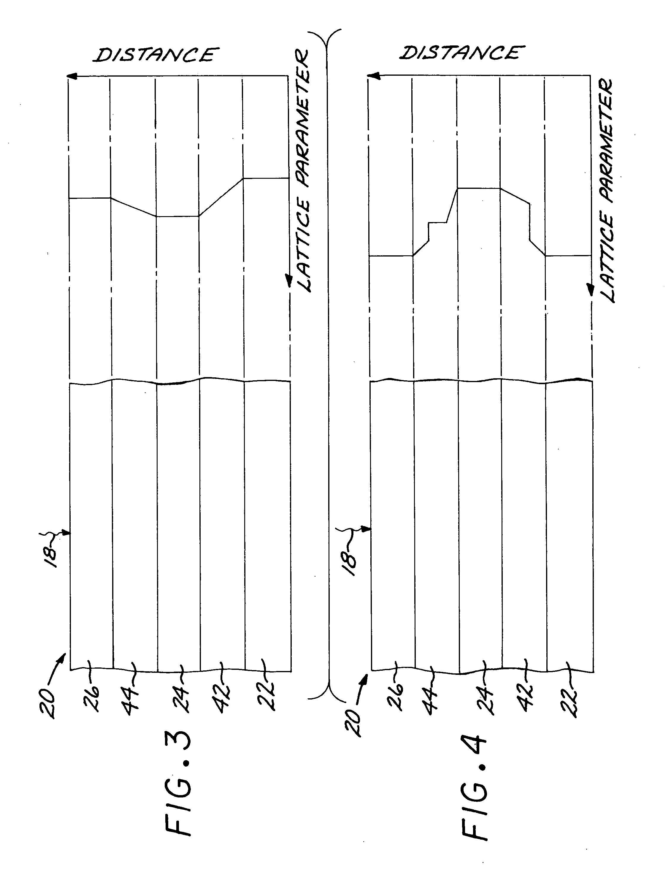
[0039]FIGS. 1-10 depict multijunction solar cells that incorporate the present approach. In each of these multijunction solar cells, sunlight from the sun is incident in a direction 18, and there are electrodes (not shown) to conduct the electrical current generated by the solar cell. When used to compare two layers, “upper” or “above” or “overlying” refers to a layer closer to the sun, and “lower” or “below” or “underlying” refers to a layer further from the sun or other source of illumination.

[0040]FIG. 1 depicts a first embodiment of a multijunction solar cell 20. The multifunction solar cell 20 includes a first layer 22 having a first-layer-lattice parameter. The first layer 22 may be an inert substrate, or it may be a photoactive layer made of a photoactive first-layer material. The multijunction solar cell 20 further includes a second layer 24 having a second-layer lattice parameter different from the first-layer lattice parameter. The second layer 24 includes a photoactive s...


PUM


Abstract

A solar cell includes a first layer having a first-layer lattice parameter, a second layer having a second-layer lattice parameter different from the first-layer lattice parameter, wherein the second layer includes a photoactive second-layer material; and a third layer having a third-layer lattice parameter different from the second-layer lattice parameter, wherein the third layer includes a photoactive third-layer material. A transparent buffer layer extends between and contacts the second layer and the third layer and has a buffer-layer lattice parameter that varies with increasing distance from the second layer toward the third layer, so as to lattice match to the second layer and to the third layer. There may be additional subcell layers and buffer layers in the solar cell.

Description

[0001] This invention was made with Government support under Contract No. F29601-98-2-0207 awarded by the United States Air Force. The Government has certain rights in this invention.[0002] The present invention generally relates to semiconductor materials and, more specifically, to solar cells. BACKGROUND OF THE INVENTION [0003] A solar cell is a photovoltaic (PV) device having one or more photovoltaic junctions. Each junction is formed by a photovoltaic semiconductor layer. At each junction, incident light energy, and specifically solar energy, is converted to electrical energy through the photovoltaic effect. [0004] The interest in solar cells has been increasing due to concerns regarding pollution and limited available resources. This interest has been for both terrestrial and non-terrestrial applications. In space applications, the use of nuclear or battery power greatly increases a spacecraft's payload for a given amount of required power to operate the satellite. Increasing t...

Claims


Application Information

Patent Timeline
Patent Type & Authority Applications(United States)
IPC IPC(8): H01L31/00
CPCH01L31/0687H01L31/1852Y02E10/544H01L31/0735Y02P70/521Y02P70/50
Inventor KING, RICHARD R.FETZER, CHRISTOPHER M.COLTER, PETER C.
Owner THE BOEING CO
Why Eureka
Try Eureka