Gas sensing element

a technology of gas sensing element and sensor output, which is applied in the direction of measurement devices, material electrochemical variables, instruments, etc., can solve the problems of inability to achieve stable combustion, large amount of nox or other air pollution gases in the exhaust gas discharged from this engine, and less actual state of exhaust gas, so as to reduce or eliminate the rich shift in the sensor output, reduce the diffusion resistance, and prevent water vapor pressure

Inactive Publication Date: 2005-12-15
DENSO CORP +1
View PDF15 Cites 26 Cited by
  • Summary
  • Abstract
  • Description
  • Claims
  • Application Information

AI Technical Summary

Benefits of technology

[0015] Next, functions and effects of the present invention will be explained. As defined above, the gas sensing element according to this invention has the porous member having the average pore diameter equal to or greater than 2 μm. This is effective in reducing the diffusion resistance. And, the water adhering to the porous member can be promptly discharged to the outside.
[0016] More specifically, water vapors contained in the measured gas atmosphere possibly adhere to the porous member. When the internal combustion engine starts its operation, the water can remove from the porous member due to the heat. The water can promptly exit to the outside because the porous member has a relatively larger average pore diameter as described above. Hence, the gas sensing element of this invention can prevent the water vapor pressure from undesirably increasing in the chamber space and also can reduce or eliminate the rich shift in the sensor output.
[0017] Furthermore, having the average pore diameter equal to or greater than 2 μm brings an effect of reducing the surface area of the porous member exposed to the measured gas, an effect of reducing an adsorption amount of the water in the measured gas, and an effect of suppressing generation of the rich shift phenomenon.
[0018] Furthermore, the gas sensing element according to this invention has the porous member having the average pore diameter equal to or less than 30 μm. This is effective in suppressing the amount of harmful substances (including Pb, P, and S) which may enter into the chamber space. Accordingly, the electrode materials can be prevented from being exposed to such harmful substances.
[0019] As described above, the present invention can provide a gas sensing element capable of suppressing the rich shift phenomenon appearing in the sensor output.

Problems solved by technology

This rich shift phenomenon is a major cause of unstable combustion occurring in an automotive internal combustion engine.
However, the actual state of exhaust gas is leaner than the indication value of the air-fuel ratio sensor.
Accordingly, the engine may cause misfires and will stop.
Furthermore, when the air-fuel ratio of the engine is greatly deviated from a target control point, the exhaust gas discharged from this engine will contain a great amount of NOx or other air pollution gases.
However, automotive vehicles are stationarily parked for a long time.
Thus, the gas sensor is inevitably subjected to such a highly-humid environment and accordingly tends to cause the above-described rich shift phenomenon.

Method used


Image

  • Gas sensing element
  • Gas sensing element
  • Gas sensing element

Examples


first embodiment

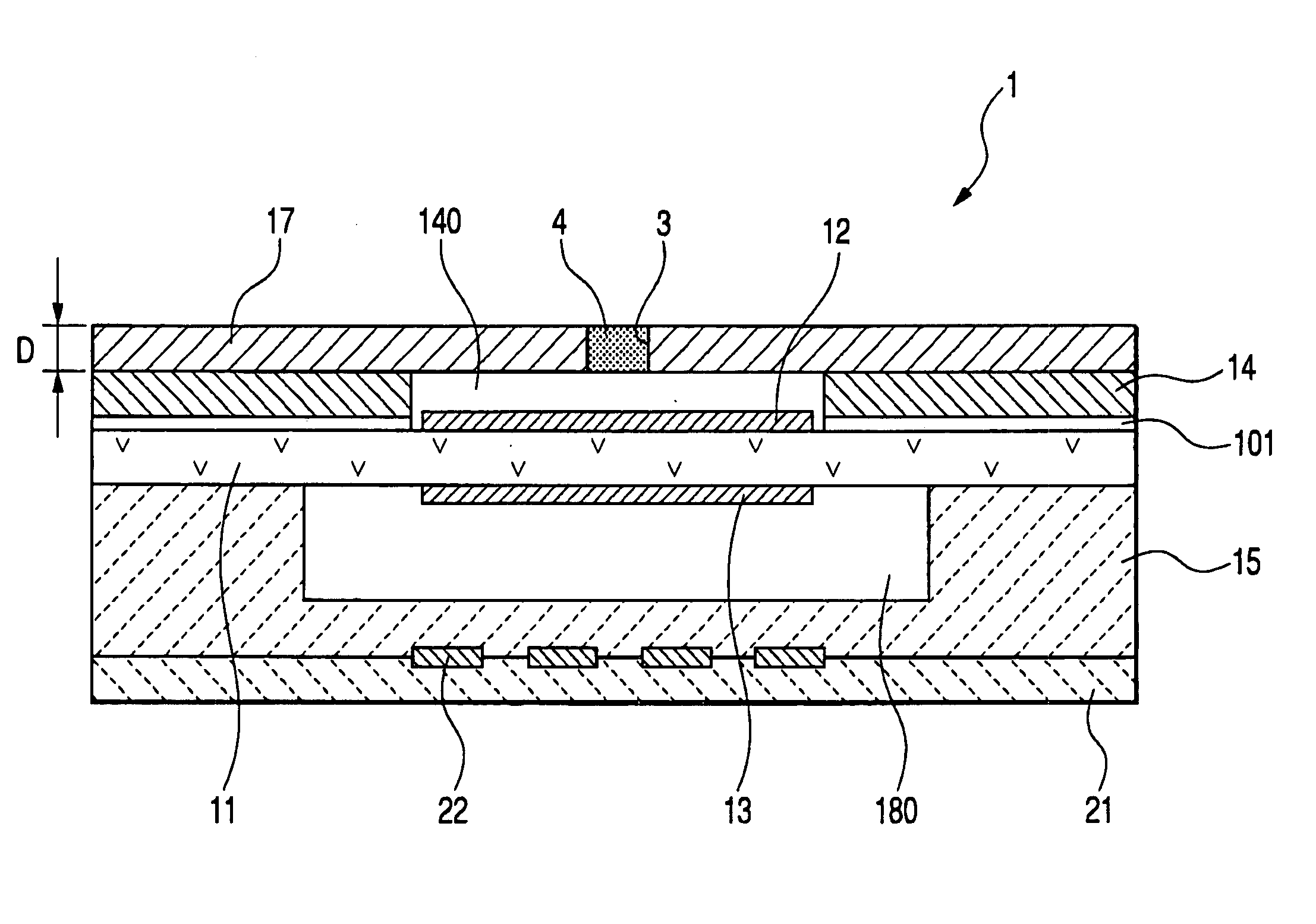
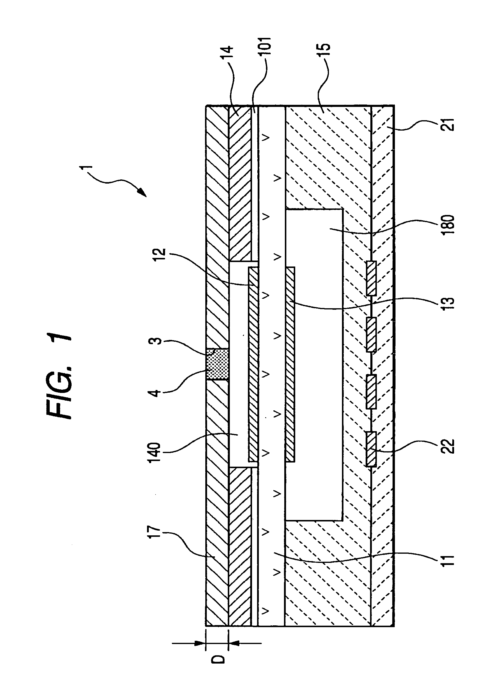
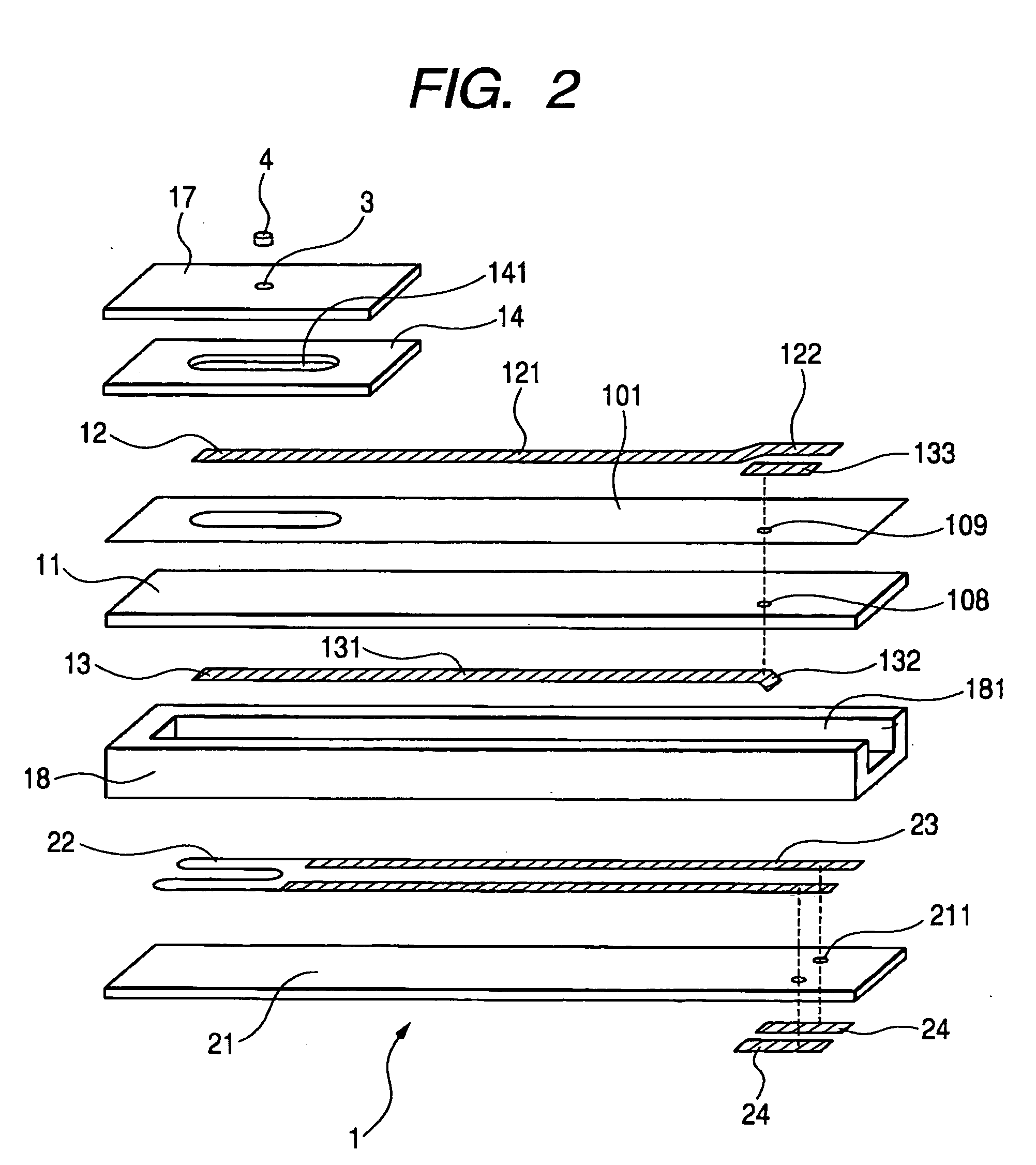
[0058] A gas sensing element in accordance with a first embodiment of the present invention will be explained with reference to FIGS. 1 to 4. A gas sensing element 1 of this embodiment includes a solid electrolyte body 11 having oxygen ionic conductivity, a measured gas side electrode 12 provided on one surface of solid electrolyte body 11, and a reference gas side electrode 13 provided on the other surface of solid electrolyte body 11. Furthermore, the gas sensing element 1 includes a chamber space 140 in which the measured gas side electrode 12 is positioned. The gas sensing element 1 has an introducing hole 3 connecting the chamber space 140 to a measured gas atmosphere outside of the gas sensing element 1. The introducing hole 3 is filled with the porous member 4 having an average pore diameter equal to or greater than 2 μm. Furthermore, the porous member 4 has the porosity of 30 to 75% by volume.

[0059] The gas sensing element 1, as shown in FIGS. 1 and 2, includes a chamber fo...

second embodiment

[0080] This embodiment is, as shown in FIGS. 5 and 6, characterized in that the gas sensing element 1 of the first embodiment is modified in that the introducing hole 3 has a cross-sectional area changing in accordance with the distance from the chamber space 140. For example, as shown in FIG. 5, it is preferable to form the introducing hole 3 whose cross-sectional area becomes larger when the distance from the chamber space 140 increases. To the contrary, as shown in FIG. 6, it is possible to form the introducing hole 3 whose cross-sectional area becomes smaller when the distance from the chamber space 140 increases.

[0081] Furthermore, according to this embodiment, the overall cross-sectional area T at the narrowest portion of the introducing hole 3, the thickness D of the shielding layer 17, and the area S of the shielding layer 17 facing to the chamber space 140 are in the relationships of 0.005≦T / D2≦0.5 and 1.0×10⁻⁵≦T / S≦5.0×10⁻³. According to this embodiment, as apparent from F...

third embodiment

[0087] This embodiment is, as shown in FIGS. 8 and 9, a gas sensing element 1b characterized in that the introducing hole 3 is formed in the chamber forming layer 14. The introducing hole 3 of this embodiment extends in a direction normal to the axial direction of gas sensing element 1b so as to connect the chamber space 140 to the measured gas atmosphere outside of the gas sensing element 1b.

[0088] More specifically, the introducing hole 3 consists of two slits each extending in the direction normal to the axial direction of gas sensing element 1b from an open portion 141 of the chamber forming layer 14 to the outside of the gas sensing element 1b. Each slit of the introducing hole 3 is filled with the porous member 4. Furthermore, the porous member 4 can be formed before sintering the green sheet of chamber forming layer 14. For example, after the introducing hole 3 is formed in the green sheet of chamber forming layer 14, the introducing hole 3 is filled with the above-described...


PUM

PropertyMeasurementUnit
pore diameteraaaaaaaaaa

Abstract

A gas sensing element includes a solid electrolyte body having oxygen ionic conductivity, a measured gas side electrode provided on one surface of the solid electrolyte body, and a reference gas side electrode provided on the other surface of the solid electrolyte body. The measured gas side electrode is positioned in a chamber space. The gas sensing element has an introducing hole connecting the chamber space to a measured gas atmosphere outside of the gas sensing element. The introducing hole is filled with a porous member having an average pore diameter of 2 to 30 μm.

Description

CROSS-REFERENCE TO RELATED APPLICATION [0001] This application is based upon and claims the benefit of priority from earlier Japanese Patent Application No. 2004-175368 filed on Jun. 14, 2004 and the Japanese Patent Application No. 2005-117356 filed on Apr. 14, 2005 so that the descriptions of which are incorporated herein by reference. BACKGROUND OF THE INVENTION [0002] The present invention relates to a gas sensing element used for controlling the combustion in an internal combustion engine, such as an automotive engine. [0003] A gas sensor (e.g. an A / F sensor), provided in an exhaust system of an automotive internal combustion engine, detects an air-fuel ratio based on the oxygen concentration in exhaust gas. For example, it is possible to perform a combustion control of the internal combustion engine based on the detected air-fuel ratio. This is generally referred to as exhaust gas control feedback system. Especially, to efficiently purify the exhaust gas with a ternary catalyst...

Claims


Application Information

Patent Timeline
Patent Type & Authority Applications(United States)
IPC IPC(8): G01N27/26G01N27/407
CPCG01N27/4071G01N27/4072
Inventor NAITO, SUSUMUIMAMURA, HIROO
Owner DENSO CORP
Why Eureka
Try Eureka