Optical head device and optical information recording or reproducing device

Inactive Publication Date: 2005-12-15
NEC CORP
View PDF9 Cites 10 Cited by
  • Summary
  • Abstract
  • Description
  • Claims
  • Application Information

AI Technical Summary

Benefits of technology

[0028] In the optical head device and the optical information recording or reproducing device of the present invention, the optical system can be reduced in size by using a plural-wavelength light source. Also, by using the diffractive optical element containing a material with a double refractive characteristic, it becomes possible to set the ratio of light quantities of the main beam and the sub-beams and the space therebetween on the optical recording medium individually for a plurality of light beams of different wavelengths. Thus, it is possible to obtain a stable error track signal by the differential push-pull method. Further, by using the polarizing beam splitter as the light separating element, the polarization directions of a plurality of the light beams of different wavelengths making incidence to the polarizing beam splitter from the diffractive optical element side can be matched with the polarization direction by which the light making incidence to the polarizing beam splitter from the diffractive optical element side is guided to the optical recording medium side with almost no loss. Thereby, loss of the light quantities of the inwards light and outwards light can be suppressed so that the efficiency is improved.
[0029] As has been described above, the effect of the optical head device and the optical infor

Problems solved by technology

However, even if the beam splitter 36 of the optical head device shown in FIG. 1 is replaced with the combination of the polarizing beam splitter and the quarter-wave plate, loss in

Method used


Image

  • Optical head device and optical information recording or reproducing device
  • Optical head device and optical information recording or reproducing device
  • Optical head device and optical information recording or reproducing device

Examples


first embodiment

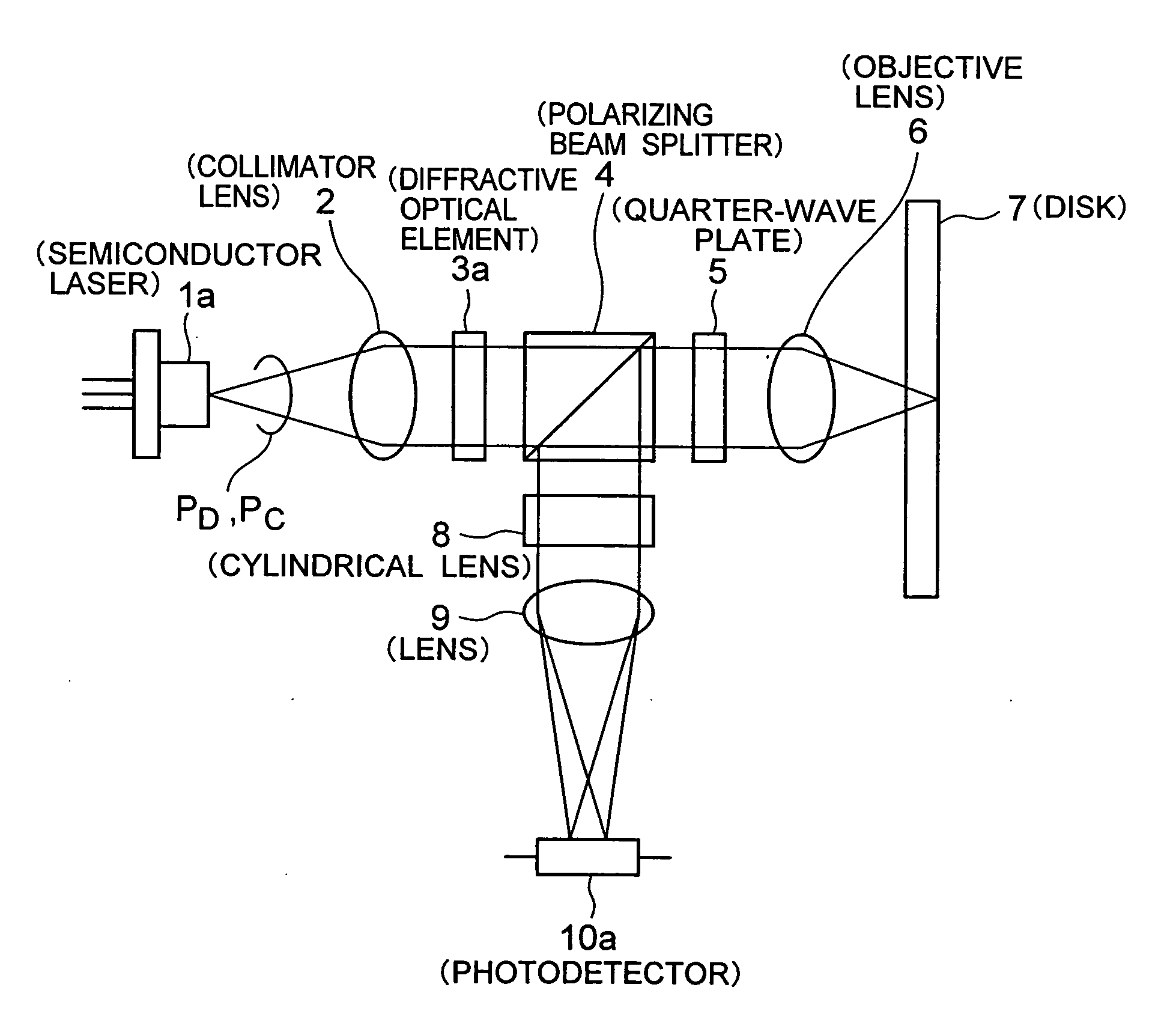
[0050]FIG. 3 shows an optical head device of the present invention. A semiconductor laser 1a comprises a semiconductor laser for emitting light PD for DVD and a semiconductor laser for emitting light PC for CD housed in a common package.

[0051] The light PD emitted from the semiconductor laser 1a is collimated by a collimator lens 2 and divided into three beams of light, i.e. the 0th-order light as the main beam and ±1st-order diffracted light as the sub-beams, by a diffractive optical element 3a. These light beams make incidence to a polarizing beam splitter 4 as P-polarized light and almost 100% transmit therethrough. The light beams transmit through a quarter-wave plate 5 and are converted from the linearly polarized light into circularly polarized light, which are then focused on a disk 7 as an optical recording medium of the DVD standard by an objective lens 6. The three light beams reflected by the disk 7 transmit through the objective lens 6 in the reverse direction and transm...

second embodiment

[0104] In the embodiment, as in the second embodiment, loss of the light quantities in the inward light and the outward light can be suppressed by matching the direction of the TM-polarized light in the diffractive optical element 3d and the direction of the P-polarized light in the polarizing beam splitter 4. Thus, the efficiency becomes high.

[0105] The functions of the diffraction gratings 16b, 16c in the diffractive optical element 3d used in the embodiment may not necessarily be the ones described in FIG. 14, as long as the diffraction grating 16b diffracts one of the light PH, the light PD or the light PC almost entirely as the 1st-order diffracted light and entirely transmits the other two light beams, and the diffraction grating 16c, among the light PH, the light PD, the light PC, diffracts either one of the two light beams (which are not diffracted in the diffraction grating 16b) almost entirely as the 1st-order diffracted light and entirely transmits the other two light bea...

third embodiment

[0107] In the third embodiment, a light spot 19p corresponds to the 0th-order light of the light PD and the light PC from the diffractive optical element 3c, which is received in four light receiving sections 25a-25d divided by a parting line which is in parallel with a direction corresponding to a tangential direction of the disk 7 passing through an optical axis and a parting line which is in parallel with the direction corresponding to the radius direction. A light spot 19q corresponds to the +1st-order diffracted light of the light PD and the light PC from the diffractive optical element 3c, which is received in four light receiving sections 25e-25h divided by the parting line which is in parallel with the direction corresponding to the tangential direction of the disk 7 passing through the optical axis and the parting line which is in parallel with the direction corresponding to the radius direction. A light spot 19r corresponds to the −1st-order diffracted light of the light P...


PUM


Abstract

Provided is an optical head device and an optical information recording or reproducing device for performing recording or reproduction to/from a plurality of types of optical recording medium, which can obtain a stable track error signal by a small size and exhibits high efficiency. Light PD and light PC emitted from a double-wavelength light source make incidence to a diffractive optical element in the same polarization directions. Diffraction gratings have a double refractive characteristic and in these areas the polarization directions of the two light beams become orthogonal. The light of 650 nm band is divided into 0th-order light and ±1st-order diffracted light in one of the diffraction grating and transmits through the other diffraction grating. The light of 780 nm band transmits through one of the diffraction grating and is divided into 0th-order light and ±1st-order diffracted light in the other diffraction grating. The two light beams are emitted from the diffractive optical element in the same polarization direction and guided towards the optical recording medium through a polarizing beam splitter and a quarter-wave plate.

Description

BACKGROUND OF THE INVENTION [0001] 1. Field of the Invention [0002] The present invention relates to an optical head device and an optical information recording or reproducing device for performing recording or reproduction to / from a plurality of types of optical recording medium and, more specifically, to an optical head device and an optical information recording or reproducing device, which can achieve a stable track error signal by small size and also exhibits high efficiency. In the followings, light of 400 nm band wavelength for HD DVD is referred to as light PH, light of 650 nm band wavelength for DVD as light PD, and light of 780 nm band wavelength for CD as light PC. [0003] 2. Description of the Related Art [0004] Optical head devices which perform recording and reproduction to / from a plurality of types of optical recording medium of different standards such as DVD (Digital Versatile Disk) and CD (Compact Disk) have been put into practical use. However, the recording or rep...

Claims


Application Information

Patent Timeline
IPC IPC(8): G11B7/135G02B5/18G11B7/00G02B5/30G02B7/04
CPCG11B7/1353G11B7/1365G11B2007/0006
Inventor KATAYAMA, RYUICHI
Owner NEC CORP
Why Eureka
Try Eureka