Bolometer infrared detector and afterimage reduction method

a technology of infrared detector and afterimage reduction, which is applied in the field ofbolometer infrared detector, can solve the problems of conventional infrared detectors and raise a serious problem for a system which acquires heat images in real time, and achieve the effect of increasing the width of a puls

Inactive Publication Date: 2005-12-15
NEC CORP
View PDF6 Cites 28 Cited by
  • Summary
  • Abstract
  • Description
  • Claims
  • Application Information

AI Technical Summary

Benefits of technology

[0019] According to the present invention with the configuration described above, when the detector detects a high temperature object whose temperature is equal to or higher than a predetermined temperature or whose output voltage is equal to or higher than a predetermined value corresponding to the predetermined temperature, the control temperature setter or the pulse bias setter

Problems solved by technology

However, these conventional infrared detectors have problems as follows.
When a high temperature object of about 500 K is imaged for about 3 minutes, for example, several minutes are required fo

Method used


Image

  • Bolometer infrared detector and afterimage reduction method
  • Bolometer infrared detector and afterimage reduction method
  • Bolometer infrared detector and afterimage reduction method

Examples


first embodiment

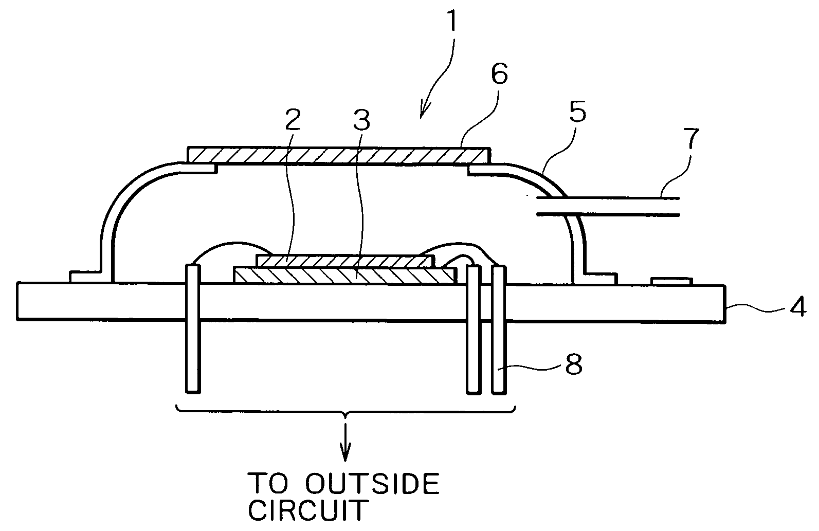
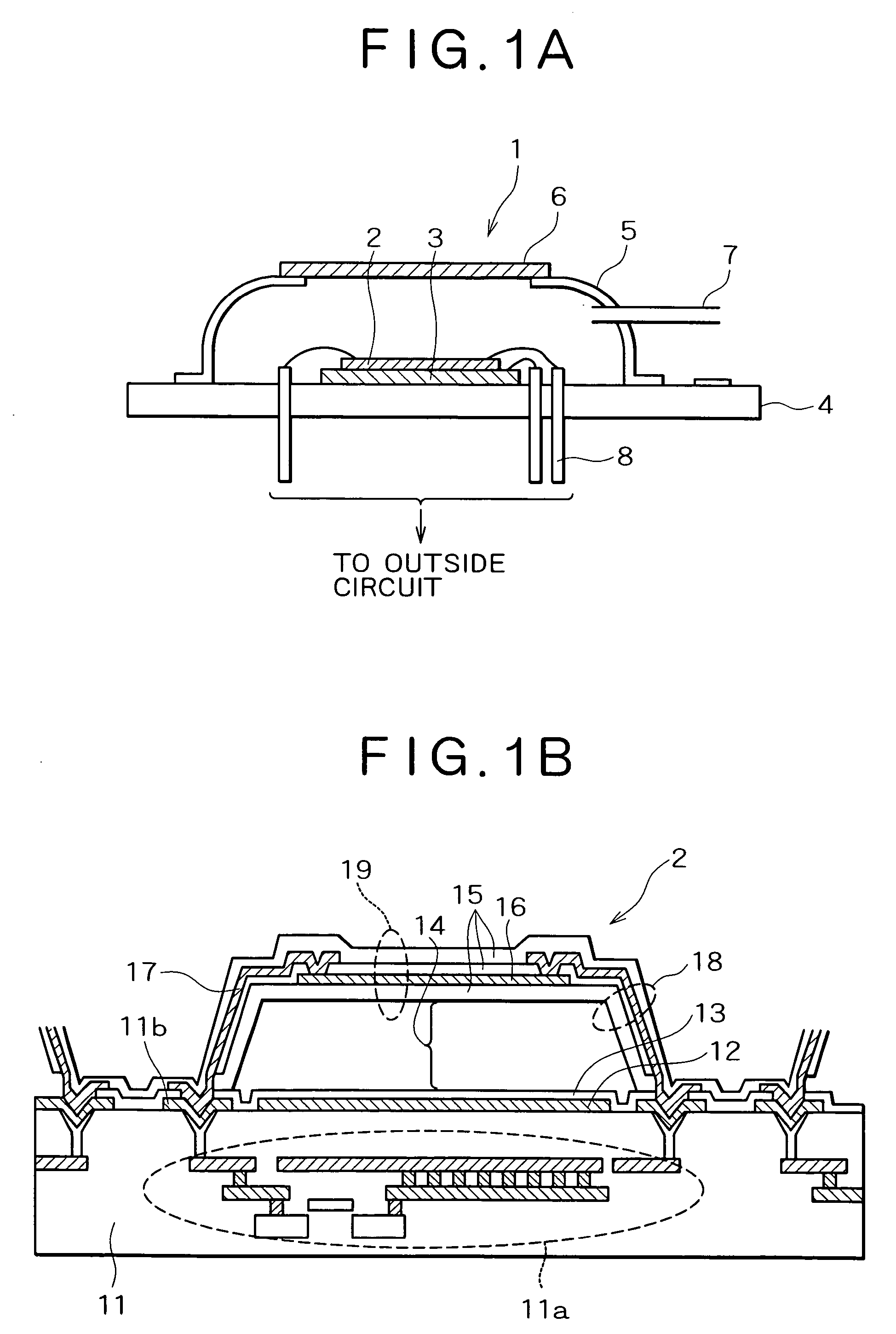
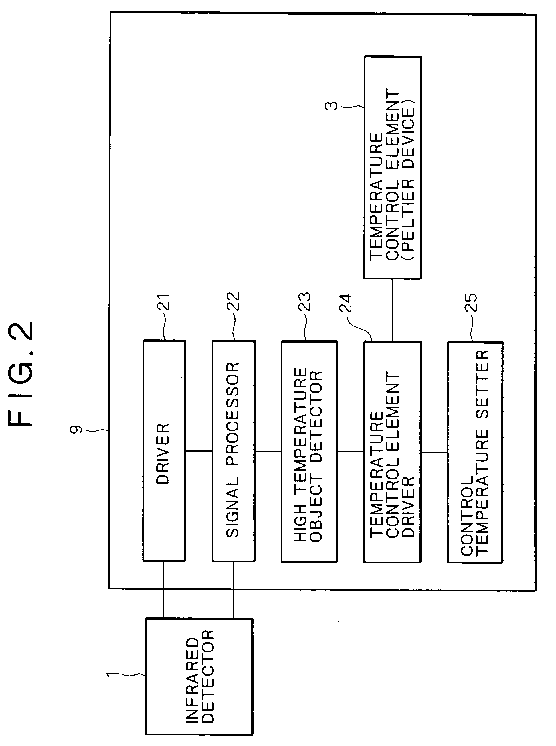
[0069] At first the bolometer infrared detector and the afterimage reduction method using the bolometer infrared detector according to the first embodiment of the present invention will be explained with reference to FIG. 1A to FIG. 4. FIGS. 1A and 1B are cross sectional views exemplarily showing the structures of the bolometer infrared detector and the infrared detecting element of the first embodiment. FIG. 2 is a block diagram showing the configuration of an external circuit of the infrared detector. FIG. 3 is a flowchart showing procedures of the afterimage reduction method. FIG. 4 is a graph showing a change in control temperature of a Peltier device.

[0070] As shown in FIG. 1A, the bolometer infrared detector 1 comprises the infrared detecting element 2 detecting infrared rays incident thereto via an optical system, a temperature control element, such as the Peltier device 3 which controls the temperature of the infrared detecting element 2, a vacuum package which comprises th...

second embodiment

[0082] The bolometer infrared detector and the afterimage reduction method using the bolometer infrared detector according to the second embodiment of the present invention will be explained next with reference to FIG. 5 and FIG. 6. FIG. 5 is a flowchart showing procedures of the afterimage reduction method. FIG. 6 is a graph showing the transition of the control temperature of a Peltier device.

[0083] In the first embodiment described above, the control temperature of the Peltier device 3 is raised every time the high temperature object detector 23 detects a high temperature object to reduce the afterimage. However, by this method, the temperature of the infrared detecting element 2 rises gradually, resulting in that the temperature coefficient of resistance (TCR) of the bolometer thin film 16 (vanadium oxide) constituting the temperature detector 19 changes and the sensitivity changes gradually. Further, power consumption for temperature control becomes large if the control temper...

third embodiment

[0090] The bolometer infrared detector and the afterimage reduction method using the bolometer infrared detector according to the third embodiment of the present invention will be explained with reference to FIG. 7 to FIG. 10. FIG. 7 is a block diagram showing the constitution of an external circuit of the bolometer infrared detector. FIG. 8 is a flowchart showing procedures of the afterimage reduction method. FIGS. 9A and 9B are graphs showing pulse bias waveforms. FIG. 10 is an explanatory graph showing the operating principle of the infrared detecting element 2.

[0091] In the first and second embodiments described above, the control temperature of the Peltier device 3 is raised to increase the temperature of the infrared detecting element 2 when the high temperature object detector 23 detects a high temperature object, thereby reducing the afterimage. However, when the control temperature of the Peltier device 3 is changed, the temperature of the whole infrared detector 1, i.e., ...


PUM


Abstract

A bolometer infrared detecting element has a thermal isolation structure in which a temperature detector comprising a bolometer thin film is held floating from a circuit substrate by beams. As infrared rays incident on the temperature detector or reflected by an infrared reflector are absorbed by a protective film and the bolometer thin film, the temperature of the bolometer thin film rises, and the temperature rise is detected as a change in resistance. When a high temperature object whose temperature is equal to or higher than a predetermined temperature or whose output voltage is equal to or higher than a value corresponding to the predetermined temperature is detected, a control temperature setter or a pulse bias setter performs control in such a way as to raise the temperature of a Peltier device stepwise or in a pulse form, or to increase the width of a pulse of pulse bias, or to increase the voltage value of the pulse. This makes it possible to raise the temperature of the infrared detecting element, thereby reducing an afterimage.

Description

BACKGROUND OF THE INVENTION [0001] 1. Technical Field of the Invention [0002] The present invention relates to a bolometer infrared detector that detects infrared rays with a thermal resistance element formed in a thermal isolation structure, and, more particularly, to a bolometer infrared detector comprising a part which reduces an afterimage and an afterimage reduction method which uses the bolometer infrared detector. [0003] 2. Description of the Related Art [0004] The infrared detector is divided broadly into a quantum detector which uses a band structure of a semiconductor and so on, and a thermal detector which uses a heat-originated change in material properties such as a resistance and a dielectric constant. The former detector has high sensitivity but needs to be cooled according to the operational principles, whereas the latter, which is called an uncooled detector because it does not require cooling, has many advantages over the quantum detector in production cost and mai...

Claims


Application Information

Patent Timeline
IPC IPC(8): H01L37/00G01J5/20G01J5/02G01J1/02H01L27/16G01J5/06
CPCG01J5/061G01J5/20G01J2005/062H01L27/16H10N19/00
Inventor ODA, NAOKI
Owner NEC CORP
Why Eureka
Try Eureka