Wind power system for energy production

a wind power system and energy production technology, applied in the direction of electric generator control, machine/engine, greenhouse gas reduction, etc., can solve the problems of wind speed variation leading to spikes in the amount of electricity generated by the generator, difficulty in selling wind generated power in the energy market, and many drawbacks of conventional wind power systems in regard to electricity generation. , to achieve the effect of low variation in the amount of electricity generated and high operational efficiency

Inactive Publication Date: 2005-12-15
HAMILTON SUNDSTRAND CORP
View PDF50 Cites 71 Cited by
  • Summary
  • Abstract
  • Description
  • Claims
  • Application Information

AI Technical Summary

Benefits of technology

[0021] The wind power system according to the present invention provides low variation in the amount of electricity generated and high operational efficiency.

Problems solved by technology

In particular, several drawbacks exist for conventional wind power systems with regard to electricity generation.
For the dedicated generator design, wind speed variation leads directly to spikes in the amount of electricity that the generator produces.
More importantly, in conventional designs the varying amount of electricity supplied to the power grid makes wind generated power difficult to sell in the energy market, which requires selling power more than twenty-four hours in advance.
When the amount of electricity generated by a conventional wind power system fails to meet the required demand, additional electricity from a remote off-site generator is transmitted to the wind power site to supplement the wind power electricity.
This introduces significant additional costs, infrastructure, and inefficiencies to the system.
Combustion engines, however, utilize conventional hydrocarbon fuels and therefore suffer considerable expense and environmental impact.
Another drawback for conventional pressurized air wind power systems is inadequate operational efficiency.
The considerable loss in efficiency can come from a variety of sources.
Another source of operational efficiency loss in conventional pressurized air wind power systems is waste of potential power from turbine rotation when the wind speed varies from a pre-selected design point.
The resulting inefficiencies lead to higher expense to produce wind generated electricity.

Method used


Image

  • Wind power system for energy production
  • Wind power system for energy production
  • Wind power system for energy production

Examples


Embodiment Construction

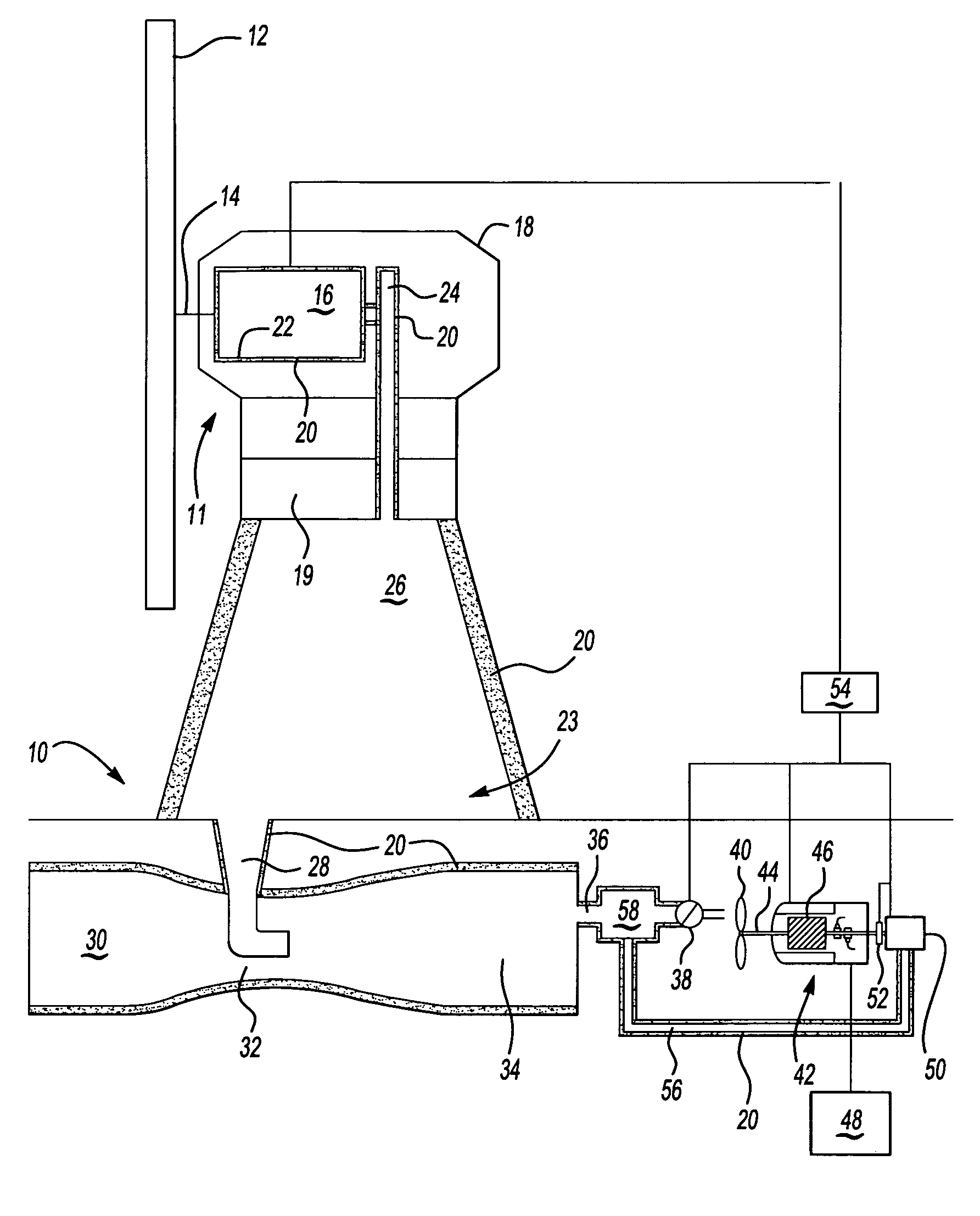
[0029]FIG. 1 illustrates a schematic view of a wind power energy system 10. The wind power energy system 10 includes a wind tower 11 with a wind turbine 12 connected to a power distributor 14. The power distributor 14 supports the wind turbine 12 and transmits power from the wind turbine 12, in response to wind, to a compression system 16 that produces pressurized air with a first temperature. The pressurized air has potential energy, including a pressure component and a temperature component. Loss of pressure and / or loss of temperature (heat) reduces the total amount of potential energy stored in the pressurized air. It is to be understood that the wind power energy system 10 typically includes multiple wind towers 11 to produce pressurized air.

[0030] A nacelle 18 houses the compression system 16. Both the compression system 16 and nacelle 18 are disposed on a yaw orientation system 19. The yaw orientation system 19 allows the nacelle 18 and wind turbine 12 to be oriented in the m...


PUM


Abstract

A wind power energy system includes a compression system that produces pressurized air with a first temperature that is received by a storage system at a second temperature that is approximately equal to the first temperature. The wind power energy system is insulated with about ten centimeters of glass-wool insulation to create an essentially adiabatic system. The pressurized air is utilized by a generator and generate electricity for a power grid. The generator also includes a combustion engine input. A control system detects fluctuation in wind power and commands the combustion engine to provide an appropriate amount of input energy to the generator such that the sum of the wind energy and combustion engine inputs produces a predetermined amount of electrical output by the generator.

Description

BACKGROUND OF THE INVENTION [0001] This invention relates to wind power energy and, more particularly, to a wind power energy system that produces a generally constant pressurized air pressure with modest heat energy loss to generate reliable electrical output. [0002] Wind power is a rapidly growing segment of the electric power generation industry. A “dedicated generator” design utilizes a wind turbine to input rotational energy directly into an electric generator to generate and supply electricity to a power grid. The wind turbine is connected to a gearbox that converts the typical fifteen to thirty revolutions per minute of the wind turbine to 1500 to 3600 revolutions per minute required for an electric generator. The gearbox is a noisy, heavy, and expensive component of the wind tower and it is generally desirable to eliminate it from the wind tower design. [0003] Another type of wind tower design utilizes a wind turbine to drive a compressor that produces pressurized air, which...

Claims


Application Information

Patent Timeline
Patent Type & Authority Applications(United States)
IPC IPC(8): F03D9/00
CPCF05B2260/231Y02E10/725F03D9/255F03D9/17Y02E60/15Y02E10/72Y02E60/16Y02E70/30
Inventor BERTOLOTTI, FABIO PAOLO
Owner HAMILTON SUNDSTRAND CORP
Why Eureka
Try Eureka