Pulsed laser apparatus and method

a laser and pulse technology, applied in the direction of electrical equipment, laser details, active medium shape and construction, etc., can solve the problems that the output efficiency of the laser cannot always be affected, and the efficiency of q-switching cannot always be effective, so as to achieve the effect of reducing the cost of operation and maintenan

Active Publication Date: 2005-12-15
LUMENTUM OPERATIONS LLC
View PDF11 Cites 14 Cited by
  • Summary
  • Abstract
  • Description
  • Claims
  • Application Information

AI Technical Summary

Benefits of technology

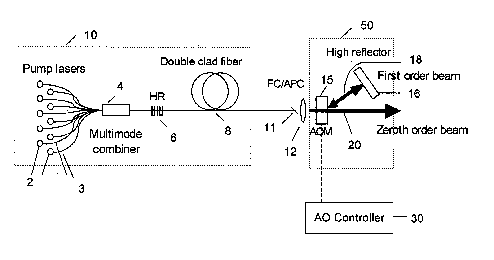
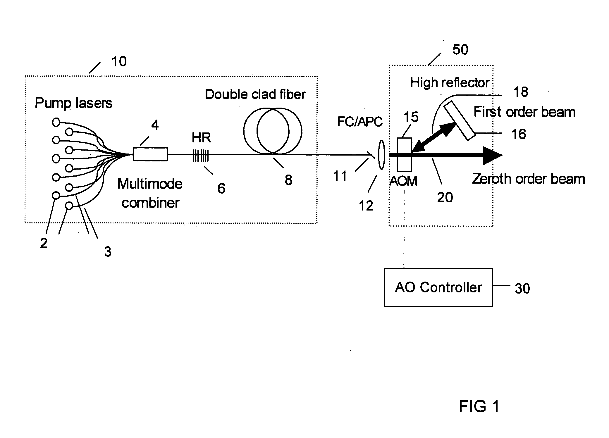
[0014] In accordance with a first aspect of the invention, a laser apparatus for generating optical pulses is provided, comprising a reflective gain element comprising first reflective means, an input/output port and a gain medium therebetween, for emitting optical radiation from the input/output port along a first optical path, and controllable reflecting/transmitting means disposed in the first optical path having a reflecting state for reflecting a controllable portion of the optical radiation back into the gain medium, and

Problems solved by technology

Pulsed operation of such fiber lasers has many applications, but offers also some new challenges.
In this case, maximum attainable loss from an AOM operating as an aforedescribed zero-order Q-switch can be insufficient to hold off the onset of lasing, and therefore this approach cannot always be used.
Relatively small modulation depth of the electro-optical tuning of the FBG described in U.S. Pat. No. 6,510,167 prevents however efficient Q-switching.
The aforedesribed prior art Q-

Method used


Image

  • Pulsed laser apparatus and method
  • Pulsed laser apparatus and method
  • Pulsed laser apparatus and method

Examples


Embodiment Construction

Definitions

[0026] Before a substantive discussion of the preferred embodiment may begin, it is essential to define several key terms.

[0027] The term “frequency” and the term “wavelength” are used in this application interchangeably. Although, frequency equals speed divided by wavelength, in fiber applications, the speed of light in a fiber is constant. Therefore, for all intents and purposes, wavelength and frequency are used interchangeably.

[0028] The term “dopant” is used in the present invention to mean any extraneous element or combination thereof, which is added to a material to enhance or suppress a characteristic of that material. Examples of dopants include, but are not limited to: germanium (Ge), hydrogen (H), neodymium (Nd), ytterbium (Yb), zirconium (Zr), zinc (Zn), erbium (Er), praseodymium (Pr), thulium (Tm), and other atomic or ionic species. The particular characteristics of interest in the present invention are the ability to act as an active or light amplifying ...


PUM


Abstract

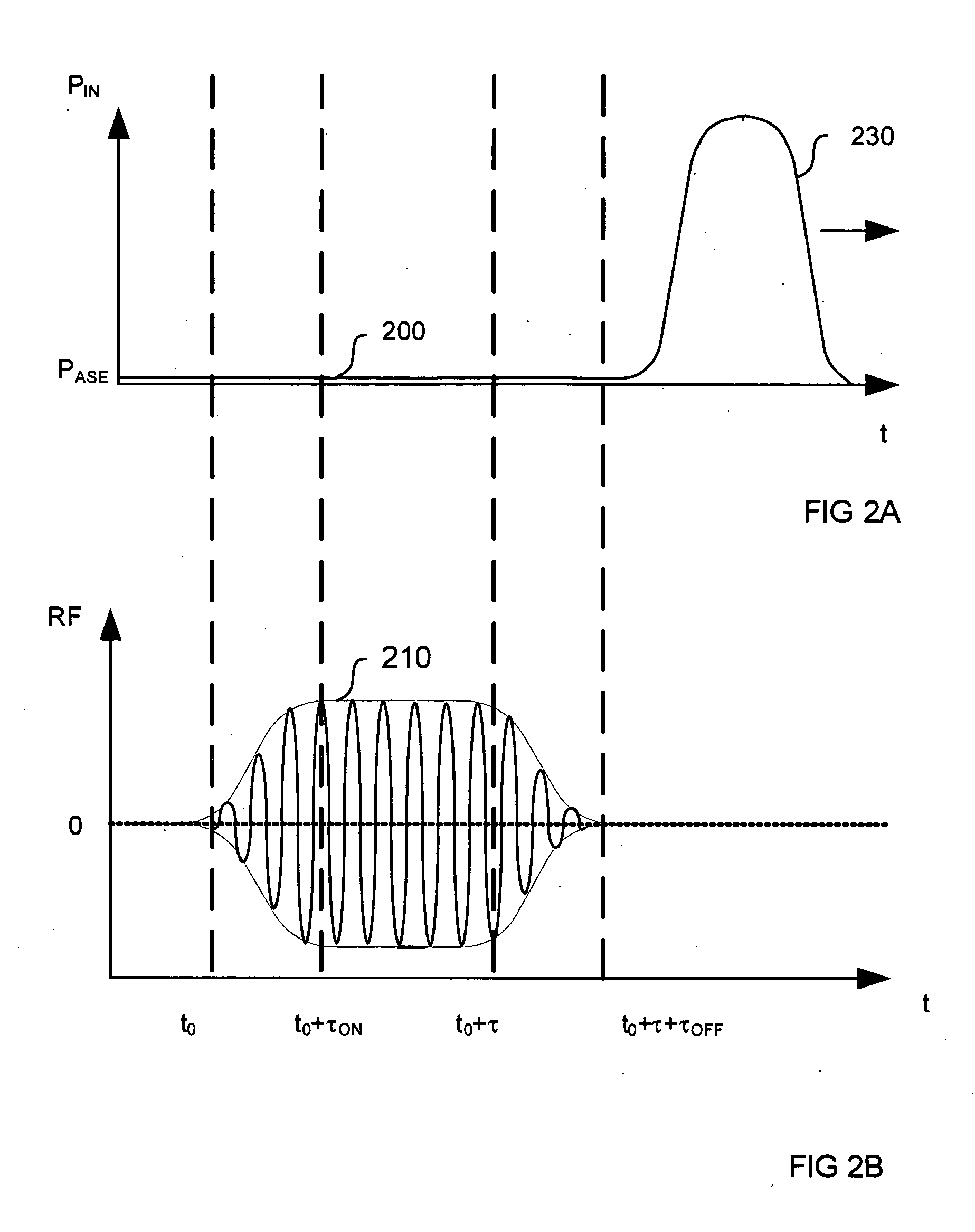
A laser apparatus for generating optical pulses is disclosed, said laser apparatus has a reflecting gain element preferably including a fiber gain medium. The reflecting gain element is coupled to a controllable reflecting/transmitting module having a reflecting state and a transmitting state, wherein the controllable reflecting/transmitting means are operable to switch from the transmitting state to the reflecting state to initiate a build-up of an optical pulse, and to switch back to the transmitting state for outputting the optical pulse before it reaches the reflecting/transmitting means after a cavity roundtrip. In a preferred embodiment, the controllable reflecting/transmitting module includes an acousto-optic switch at an output end of a laser operable to output the optical pulse in zeroth diffraction order.

Description

FIELD OF THE INVENTION [0001] The present invention relates to sources of pulsed laser radiation. This invention is particularly suitable for Q-switched fiber lasers employing intra-cavity modulators. BACKGROUND OF THE INVENTION [0002] Continuous-wave (CW) fiber lasers offer many advantages over other conventional diode pumped solid state (DPSS) lasers. Pulsed operation of such fiber lasers has many applications, but offers also some new challenges. [0003] Generally, pulsed operation of a laser can be achieved by active or passive Q-switching or active or passive mode-locking. In Q-switching of a laser, a finesse parameter of the laser cavity is temporarily reduced by insertion of additional cavity loss, thereby allowing a population inversion in the laser's active medium to increase without an onset of lasing. When the loss element, typically an acousto-optic modulator (AOM), is switched off, an optical pulse quickly builds up within a few round trips of the cavity and a giant opti...

Claims


Application Information

Patent Timeline
IPC IPC(8): H01S3/067H01S3/11H01S3/117
CPCH01S3/0675H01S3/09408H01S3/117H01S3/115H01S3/1127H01S3/1103
Inventor MACCORMACK, STUARTWAARTS, ROBERT G.
Owner LUMENTUM OPERATIONS LLC
Why Eureka
Try Eureka