Method and apparatus for performing motion compensation on video data

Inactive Publication Date: 2005-12-15
ADILETTA MATTHEW J +2
View PDF52 Cites 67 Cited by
  • Summary
  • Abstract
  • Description
  • Claims
  • Application Information

AI Technical Summary

Benefits of technology

[0016] With such and arrangement, a high quality image may be produced because bits are more optimally allocated across pictures than they are using conventional techniques. Because the reference frame is encoded prior to the dependent frames, such as B frames, more bits are available to encode the reference frame. It is inherently more important for reference frames to be optimally encoded because the reference frame is not only displayed but is used to effect encoding of up to 4 other dependent frames. Accordingly, the present invention, by delaying the compression of dependent frames until all associated reference frames have been compressed, provides a high quality image.
[0017] According to a further aspect of the invention, the method of compressing the frames further includes the steps of determining motion characteristics for each of said frames and providing compressed dat

Problems solved by technology

One drawback of this scheme arises from the fact that only a fixed number of bits are allocated for encoding a frame.
However the complexity of the process has precluded it from being a valuable tool for video compression applications which require real-time performance.
The main problem with two-pass compression techniques is encountered when analyzing B frames, as will be shown below.
As seen in FIG. 1, a problem with real-time two pass processing soon develops when encoding B frames.
Al

Method used


Image

  • Method and apparatus for performing motion compensation on video data
  • Method and apparatus for performing motion compensation on video data
  • Method and apparatus for performing motion compensation on video data

Examples


Embodiment Construction

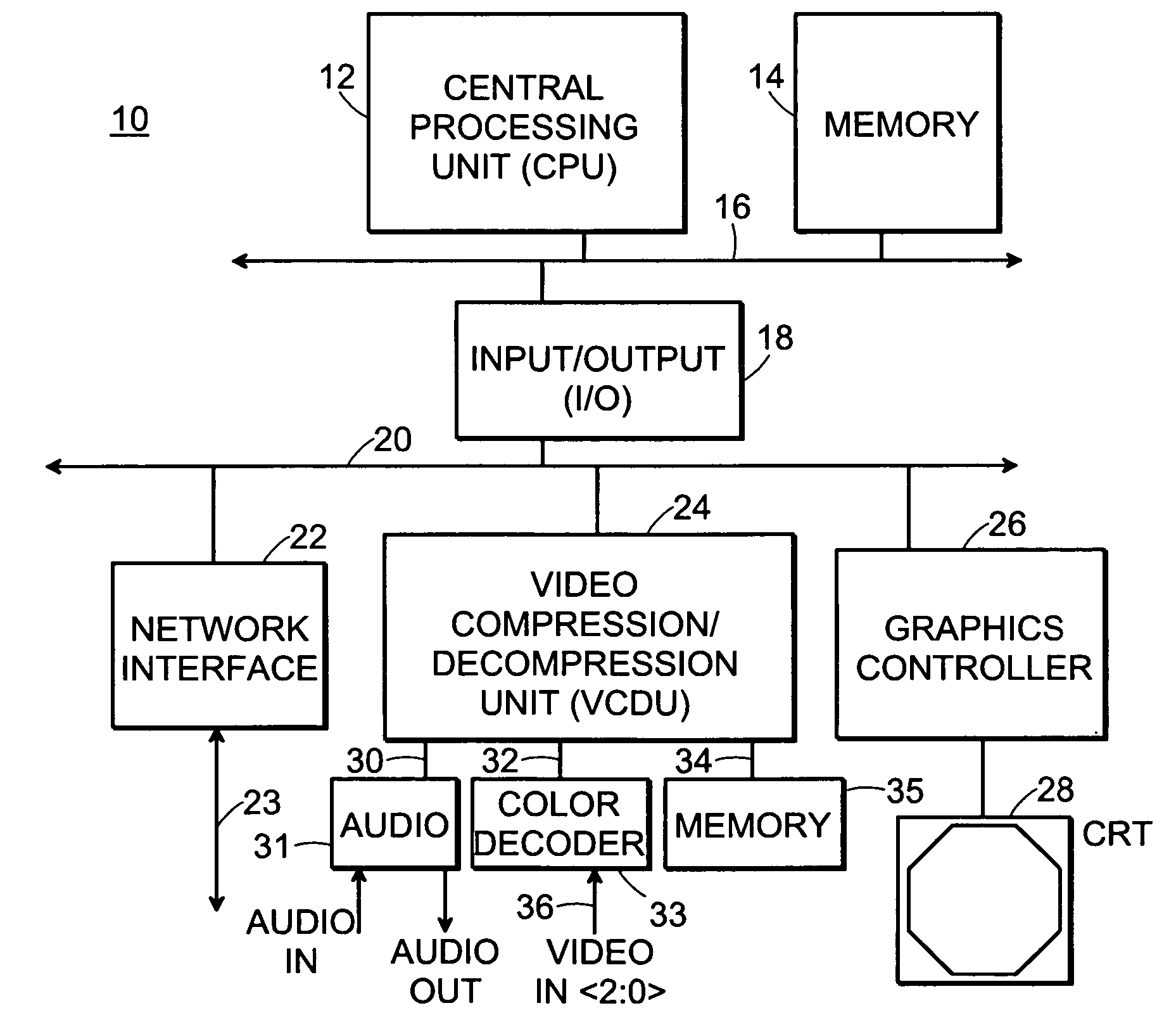
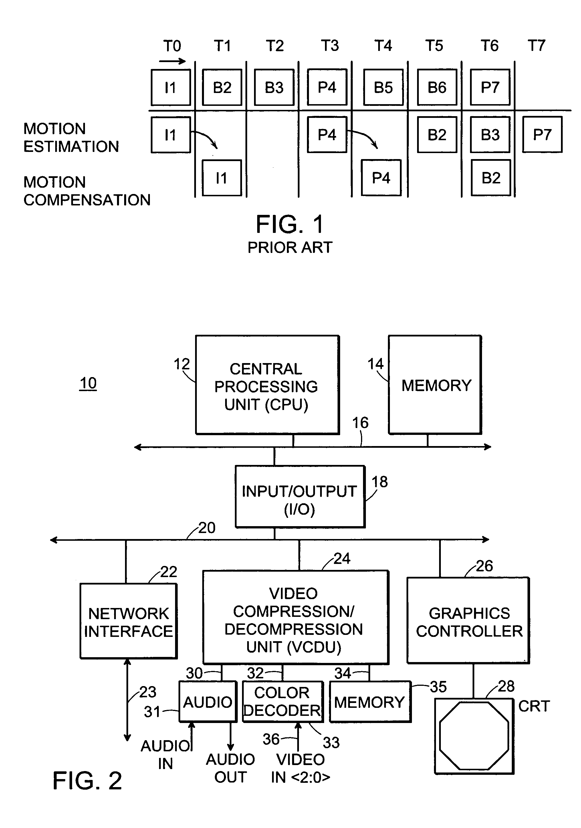
[0076] Referring now to FIG. 2, a computer system 10 for use with the present invention is shown to include a central processing unit (CPU) 12 for processing an instruction stream. The instruction stream as well as data which is used by the CPU is stored in a memory 14. The CPU 12 and the memory 14 are coupled together via a system bus 16.

[0077] Also coupled to system bus 16 is Input / Output (I / O) interface 18. The I / O interface enables the CPU to communicate with a number of external devices via an I / O bus 20. The I / O bus 20 of the present invention is operated according to the Peripheral Connect Interface (PCI™) protocol, and is capable of transferring data at 133 Mbyte / sec, although it is understood that the present invention could be modified for use with other I / O protocols by one of ordinary skill in the art.

[0078] A network interface 22 is coupled to I / O bus 20 for interfacing the CPU with other CPU's in a network. Also coupled to the PCI bus is a graphics controller 26, whi...


PUM


Abstract

An apparatus and method for performing two-pass real time video compression is provided. Tactical decisions such as encoding and quantization values are determined in software, whereas functional execution steps are performed in hardware. By appropriately apportioning the tasks between software and hardware, the benefits of each type of processing are exploited, while minimizing both hardware complexity and data transfer requirements. One key concept that allows the compression unit to operate in real time is that the architecture and pipelining both allow for B frames to be executed out of order. By buffering B frames, two-pass motion estimation techniques can be performed to tailor bit usage to the requirements of the frame, and therefore provide a more appealing output image.

Description

RELATED APPLICATIONS [0001] This application is a divisional of U.S. patent application Ser. No. 10 / 721,947 filed on Nov. 25, 2003 which is a divisional of U.S. patent application Ser. No. 09 / 613,359 filed Jul. 10, 2000 (now U.S. Pat. No. 6,760,478 issued Jul. 6, 2004) which is a continuation of U.S. patent application Ser. No. 08 / 670,199 filed on Jun. 21, 1996 (now U.S. Pat. No. 6,101,275 issued Aug. 8, 2000), the entire teachings of which are incorporated herein by reference.FIELD OF THE INVENTION [0002] This invention relates in general to computer systems and more specifically to computer video compression and decompression techniques. BACKGROUND OF THE INVENTION [0003] With the convergence of computers, communications and media, video compression techniques have become increasingly important. Video compression is often used to translate video images (from camera, VCR, laser discs, etc.) into digitally encoded frames. The digitally encoded frames may then be easily transferred o...

Claims


Application Information

Patent Timeline
IPC IPC(8): G06T9/00H04N7/12H04N7/26H04N7/32H04N7/36H04N7/46H04N7/50
CPCH04N19/159H04N19/577H04N19/46H04N19/51H04N19/149H04N19/61H04N19/114H04N19/124H04N19/127H04N19/132H04N19/14H04N19/177H04N19/82H04N19/42H04N19/31H04N19/423H04N19/436H04N19/587H04N19/87H04N19/93H04N19/176
Inventor ADILETTA, MATTHEW J.HO, SAMUEL W.SUDHARSANAN, SUBRAMANIA IYER
Owner ADILETTA MATTHEW J
Why Eureka
Try Eureka