Apparatus and method for reducing interference

a technology of interference reduction and apparatus, applied in the field of electronic methods and apparatus for reducing interference, can solve the problems of inability to obtain true simultaneous fmri and eeg data, no disclosure of a method for obtaining clean eeg, and signal with induced nois

Inactive Publication Date: 2005-12-15
CONOPCO INC D B A UNILEVER
View PDF2 Cites 54 Cited by
  • Summary
  • Abstract
  • Description
  • Claims
  • Application Information

AI Technical Summary

Benefits of technology

[0047] According to a eleventh aspect of the present invention, there is provided a method of performing a simultaneous fMRI and EPM measurement, the method comprising placing a subject in an MRI apparatus and per...

Problems solved by technology

However, a typical EEG signal obtained from a scalp electrode is in the range typically of 1 μV to 100 μV at an impedance of around 500 Ω to 50K Ω. The large magnetic and radio frequency (rf) fields produced by MRI machines easily swamp this signal with induced noise on the signal wire.
Thus, although the system purports to enable fMRI and EEG signals to be obta...

Method used


Image

  • Apparatus and method for reducing interference
  • Apparatus and method for reducing interference
  • Apparatus and method for reducing interference

Examples


first embodiment

[0076]FIG. 3 shows a circuit diagram of an electronic interference reduction apparatus according to the present invention;

second embodiment

[0077]FIG. 4 shows a circuit diagram of an electronic interference reduction apparatus according to the present invention;

[0078]FIG. 5 shows a circuit diagram of the second embodiment of FIG. 4;

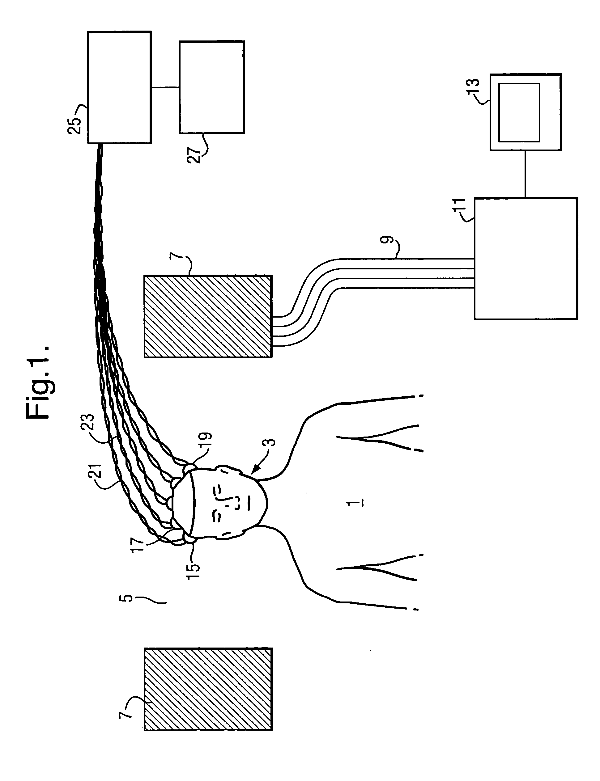
[0079]FIG. 6 shows an EEG plot obtained during tests utilising the arrangement of FIG. 1 in combination with an electronic interference reduction apparatus according to the present invention;

[0080]FIG. 7 shows an equivalent circuit of an embodiment utilising both a ground electrode and a reference electrode;

[0081]FIG. 8 shows an equivalent circuit of input circuitry suitable for use with an arrangement such as shown in FIG. 7;

[0082]FIG. 9 shows an equivalent circuit arrangement of interconnection of multiple signal electrodes on the body together with a ground electrode;

[0083]FIG. 10 shows suitable amplification, subtraction and filtering circuitry for use with arrangements generally as depicted in FIGS. 7 to 9;

[0084]FIG. 11 shows front-end circuitry forming part of a particularly prefe...


PUM


Abstract

In an electronic apparatus and method for reducing interference in an EPM signal, there is provided (a) a signal line connected to a-signal electrode; and (b) a reference line connected to a reference electrode. The signal line and reference line are associated by being in close physical proximity for a substantial part of their lengths. Subtraction means subtracts an interference signal on the reference line from an interference signal on the signal line to enhance a desired signal on the signal line.

Description

FIELD OF THE INVENTION [0001] This present invention relates to an electronic method and apparatus for reducing interference in a signal wherein the interference is of a large magnitude relative to the data component to be extracted from the signal. It is particularly, although not exclusively, suited to reducing noise in biopotential signal acquisition, which noise is caused by electrical and magnetic fields. BACKGROUND OF THE INVENTION [0002] Functional magnetic resonance imaging (fMRI) is widely used in both medical and non-medical imaging to obtain a spatial image of “slices” through the brain. In the medical context, it can be used to identify lesions such as areas of restricted blood flow or tumours. Outside the medical field, it has, for example, been a useful tool in cognitive neuroscience for investigating brain response to various external stimuli. [0003] Electroencephalography (EEG) has traditionally been used for investigations into brain activity. It may, for example, b...

Claims


Application Information

Patent Timeline
IPC IPC(8): A61B5/04A61B5/0476A61B5/0496A61B5/05G01R33/48H03F1/34H03F3/21H03F3/26H03F3/45H03H1/00
CPCA61B5/04004A61B5/0476A61B5/0496G01R33/4806H03F1/34H03F3/211H03H1/0007H03F3/45475H03F2200/321H03F2200/534H03F2203/45138H03F2203/45526H03F3/26A61B5/30A61B5/369A61B5/398
Inventor DUNSEATH, WILLIAM JAMES ROSS JR.
Owner CONOPCO INC D B A UNILEVER
Why Eureka
Try Eureka