Cylinder block

a technology of cylinder block and cylinder head, which is applied in the direction of machines/engines, foundry patterns, machine/engine layout, etc., can solve the problems of affecting the sealing ability of the gasket at the deck surface, affecting the flexibility of engine layout design, and affecting the axial fastening force of the head bolt, etc., to achieve high rigidity, low coefficient of thermal expansion, and high thermal conductivity

Inactive Publication Date: 2005-12-22
HONDA MOTOR CO LTD
View PDF1 Cites 9 Cited by
  • Summary
  • Abstract
  • Description
  • Claims
  • Application Information

AI Technical Summary

Benefits of technology

[0043] According to some of the above-described embodiments of the present invention, the increase in axial fastening force applied to the head bolt, which would be caused by change in temperature of the engine, can be checked or minimized, so that a cylinder block in which the axial fastening force applied to the head bolt can be maintained irrespective of change in temperature of the engine (whether the engine is under high

Problems solved by technology

Consequently, head bolts having a larger diameter enough to exhibit a strength required to endure the axial fastening force corresponding to the selected higher grade of strength for the head bolts should be provided, which would disadvantageously restrict flexibility in designing an engine layout, or offer some other problems.
When the cylinder block made of an aluminum alloy having a greater coefficient of thermal expansion expands and contracts due to change in temperature resulting from operation of the engine, the axial fastening force of the head bolts would change considerably, which would disadvantageously impair the sealing capability of the gasket at the deck surface.
However, the reinforcements of the cylinder block as disclosed in JP 2002-224816 A are made by integrally embedding into the cylinder block a metal porous body composed of a stainless steel such as Fe, Cr and Ni, and are thus heavier in mass in comparison with metal materials, such as aluminum alloys, making up the cylinder block, which would place the cylinder block at disadvantages in achieving weight and size reduction.
The cylinder block as disclosed in JP 2002-224816 A is adapted to improve the slidability of the bore, but when increase in output of an engine of the same type is desired, the engine could not help undergoing major design changes in order to attend to the associated increase in heat load and combustion pressure; this would entail the problems as follow

Method used


Image

  • Cylinder block
  • Cylinder block
  • Cylinder block

Examples


first embodiment

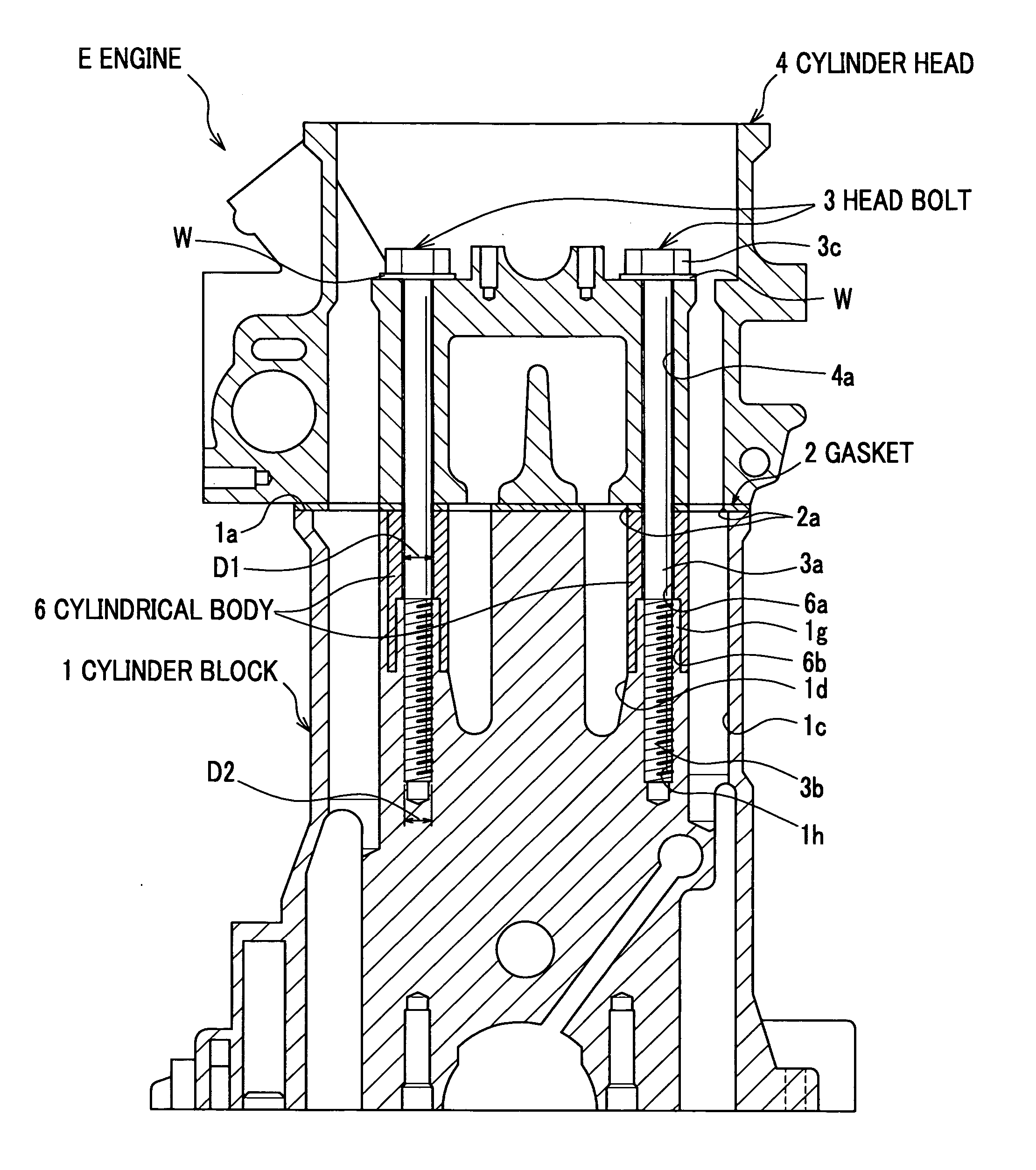
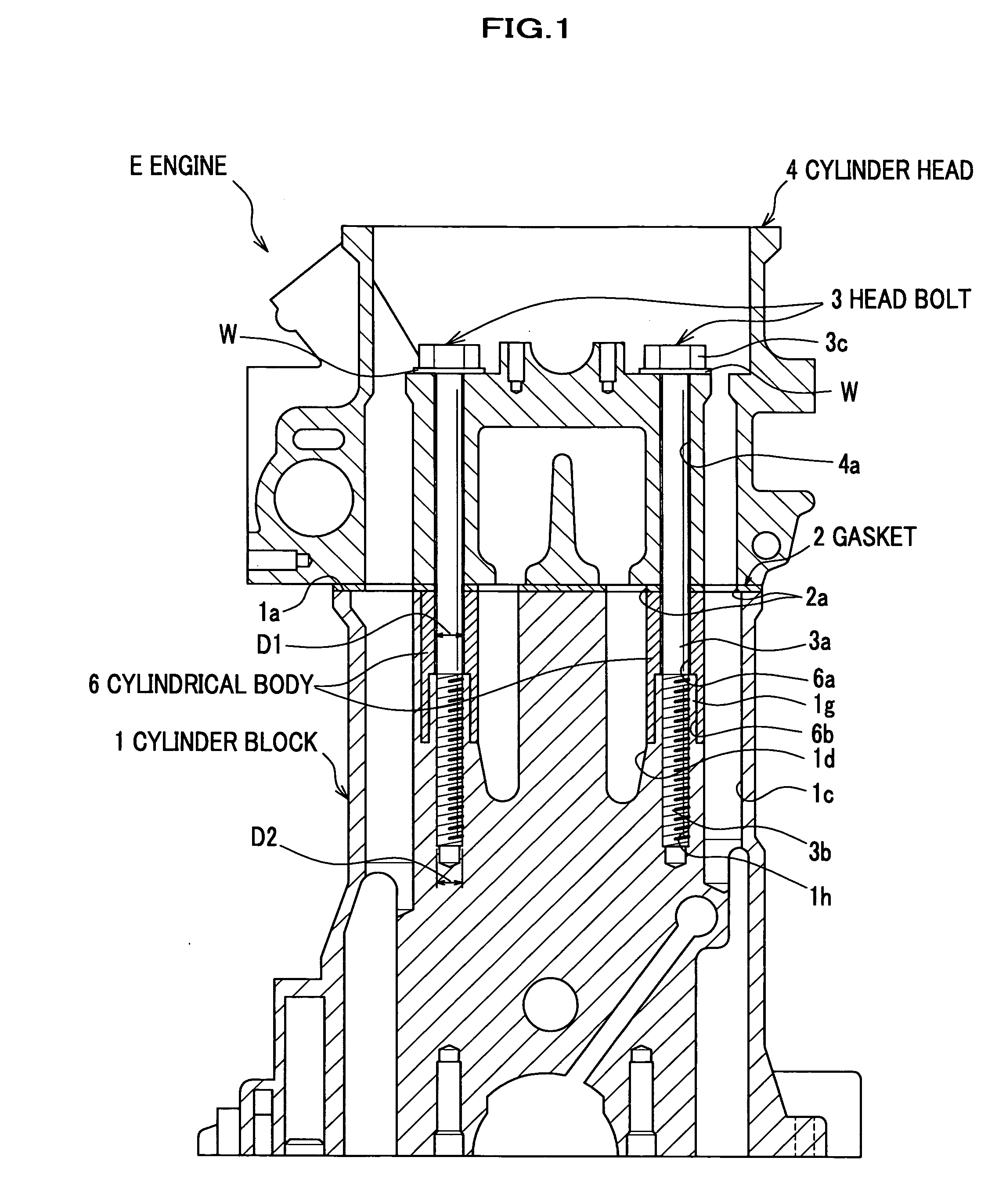
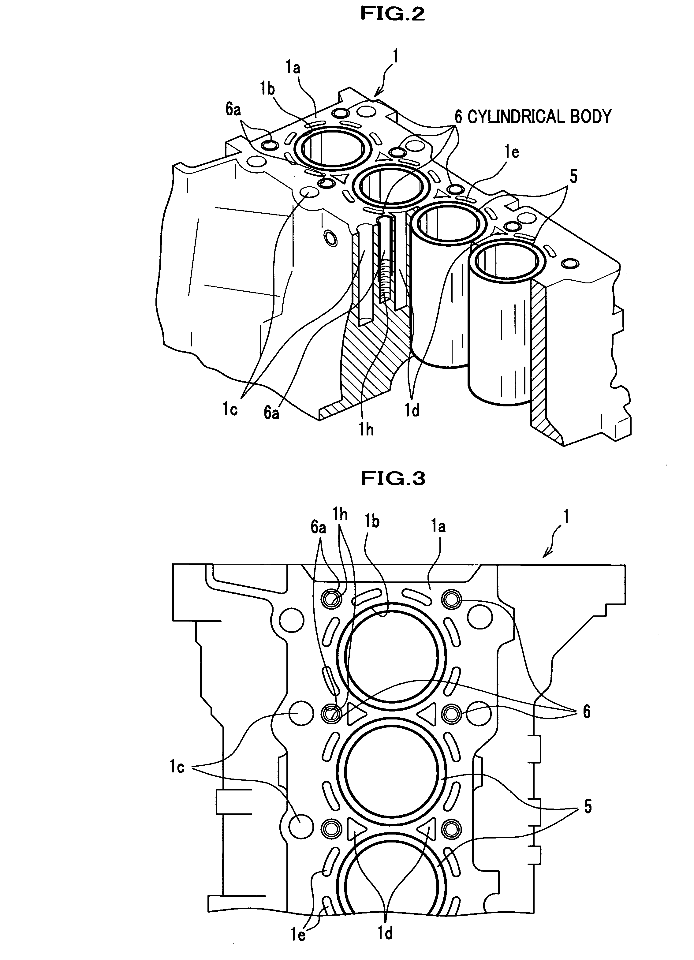
[0061] Referring now to FIGS. 1-3, a description will be given of a cylinder block according to a first embodiment of the present invention, to which a cylinder head is to be fastened using head bolts. In the first embodiment of the present invention, a portion of the cylinder block around each bolt hole thereof for a head bolt to be inserted therethrough is formed of a metal matrix composite (MMC) that will be described later in detail. In the following description of the present embodiment, the portion formed of the metal matrix composite will be called “cylindrical body”.

[0062] As shown in FIG. 1, an engine E includes a cylinder block 1, and a cylinder head 4 fastened to a top face (deck surface 1a) of the cylinder block 1 using a plurality of head bolts 3 with a gasket 2 placed between the cylinder head 4 and the cylinder block 1.

[0063] Further provided in the engine E are a head cover (not shown) disposed over a top face of the cylinder head 4, and a lower case (not shown) di...

second embodiment

[0123] Referring now to FIGS. 10-14, a description will be given of a cylinder block according to a second embodiment of the present invention, in which cylinder liners are provided. In the second embodiment of the present invention, each of the cylinder liners provided inside bores is formed of a metal matrix composite (MMC). In the drawing figures to which a reference will be made, the same components as in the first embodiment are designated by the same reference characters, and a duplicate description thereof will not be given.

[0124] As shown in FIGS. 10 and 11, the cylinder block 1 is molded of a metal 12 (see FIG. 5) such as an aluminum alloy with which cylindrically shaped ceramic compacts 7 (preforms of cylinder liners 5′, see also FIG. 4) are filled, so that the cylinder block 1 and the cylinder liners 5′ are of monolithic construction. The cylinder block 1 is made by placing the ceramic compacts 7 as inserts in a mold and pouring the metal 12 in the mold. At the deck surf...


PUM


Abstract

In a cylinder block, at least one member disposed around a bore is made of a metal matrix composite including a ceramic compact having a three-dimensional mesh structure comprised of a plurality of spherical cells and a plurality of communicating pores for allowing adjacent spherical cells to communicate with each other, with the plurality of spherical cells filled with a metal.

Description

CROSS-REFERENCE TO RELATED APPLICATIONS [0001] This application claims the foreign priority benefit under Title 35, United States Code, § 119 (a)-(d), of Japanese Patent Application Nos. 2004-177771 and 2004-177773, filed on Jun. 16, 2004 in the Japan Patent Office, the disclosure of which is herein incorporated by reference in its entirety. BACKGROUND OF THE INVENTION [0002] This invention relates to a cylinder block of an internal combustion engine. [0003] Typically, the cylinder block of the engine has a deck surface and a cylinder head is fastened over the deck surface using so-called “head bolts”, with a head gasket (hereinafter referred to simply as “gasket”) placed between the cylinder block and the cylinder head. See for example JP 2000-240502 A, paragraphs 0019-0026, FIGS. 1-5. [0004] In this instance, the cylinder block and the cylinder head provided in the engine are die-cast components formed of a light alloy for weight reduction. The cylinder block, gasket and cylinder ...

Claims


Application Information

Patent Timeline
IPC IPC(8): F02F1/00F02F1/10F02F7/00
CPCF02F7/0085F02F1/10
Inventor YAMAMURA, SATOSHISHIBATA, KAZUOOHYA, TADASHI
Owner HONDA MOTOR CO LTD
Why Eureka
Try Eureka