Holdover circuit for a power converter using a bi-directional switching regulator

Active Publication Date: 2005-12-22
TEXAS INSTR INC
View PDF17 Cites 15 Cited by
  • Summary
  • Abstract
  • Description
  • Claims
  • Application Information

AI Technical Summary

Benefits of technology

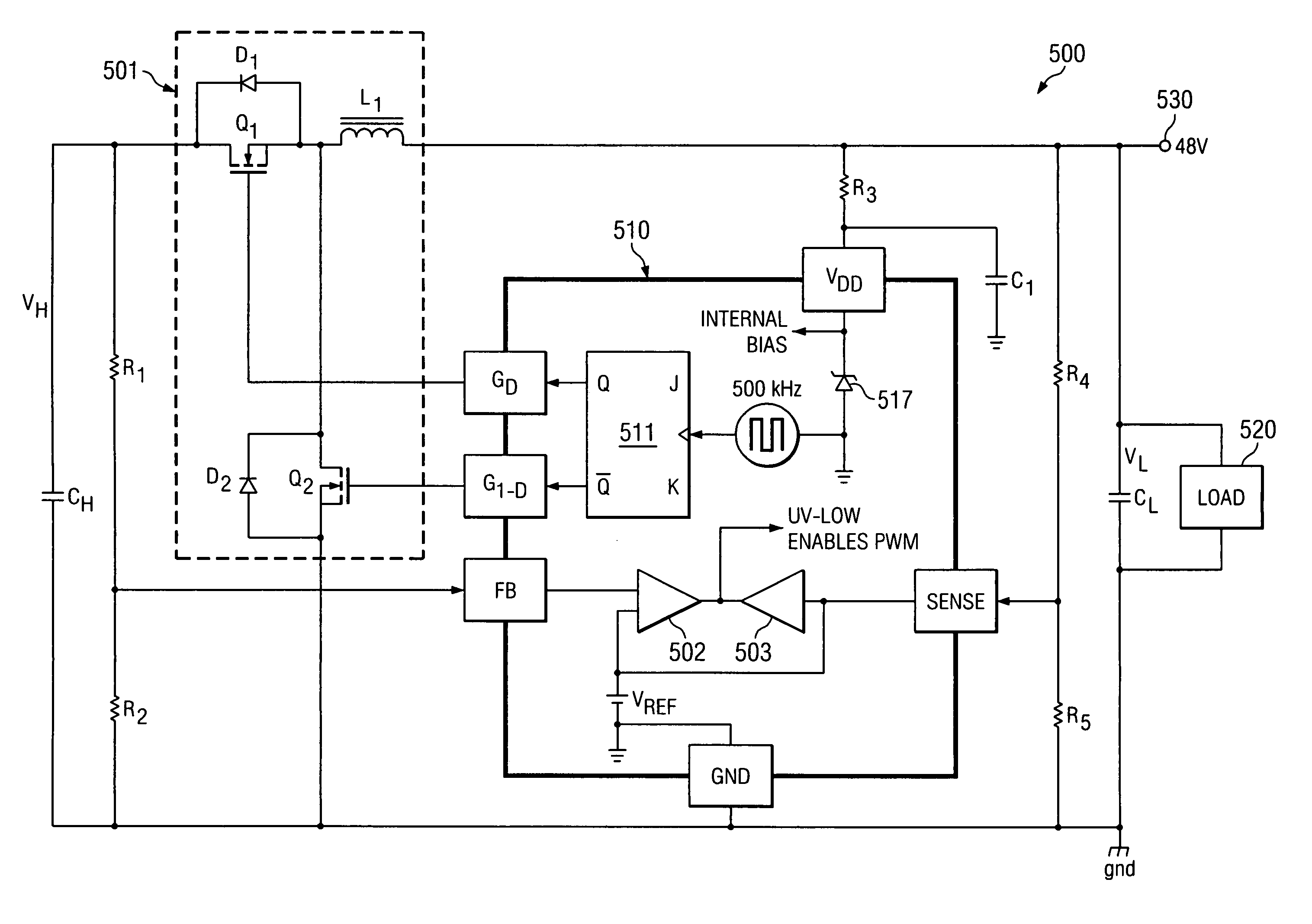
[0019] Another embodiment of the present invention is a method of configuring a holdover circuit to protect an electrical load powered from an input voltage source and operable over a range of input voltages. The method includes configuring the holdover circuit with a holdover capacitor and charging the holdover capacitor to a voltage to provide an energy source to power the load during brief power interruptions. The method includes coupling a switching regulator between the load and the holdover capacitor, including two power switches in the switching regulator so that the holdover capacitor can be charged and discharged at a voltage different from the voltage of the load. Preferably, the method includes configuring the switching regulator to maintain the voltage of the holdover capacitor at a voltage higher than the voltage of the load. Preferably, the method includes configuring the two power switches in the switching regulator as active switches and controlling the switches with complementary duty cycles. The method includes configuring the switching regulator to regulate the voltage of the holdover capacitor at a voltage pr

Problems solved by technology

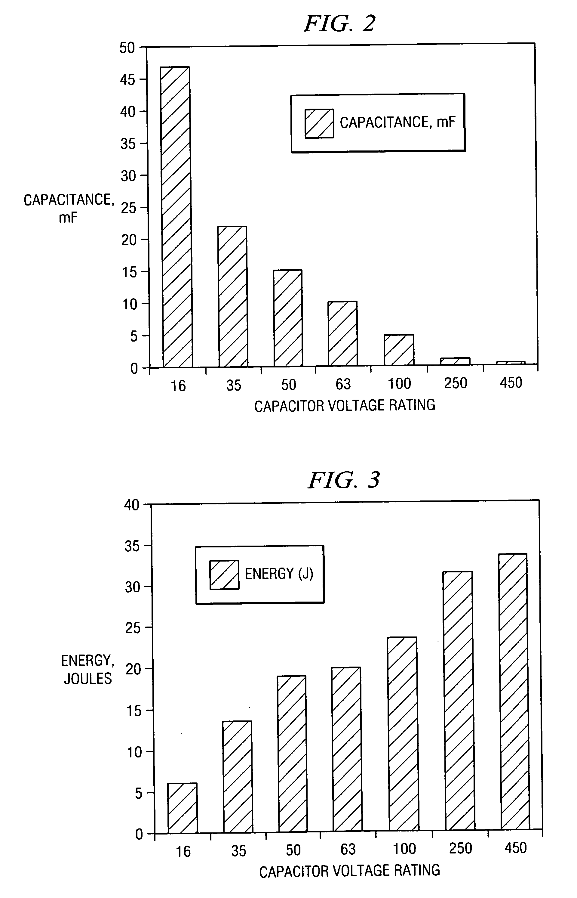
Such uninterruptible operation with no or very little input voltage is often referred to as “holdover,” and usually requires the addition of capacitors of significant size to the circuit to provide the necessary holdover energy.
Capacitors generally are not a volumetrically efficient means for energy storage.
This capacitance could be implemented with 56 capacitors, each rated at 100 microfarads, which would consume a substantial amount of board space, incur significant expense in fabricating a 200 watt power converter, and introduce reliability issues due the large number of additional circuit components required in the product design.
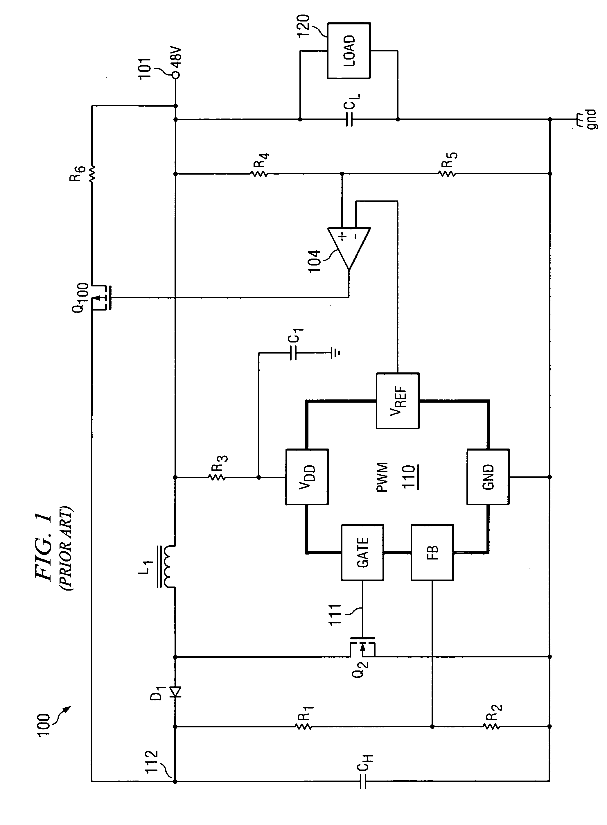
Nonetheless, it still has limitations because the voltage of the capacitor CH, which is directly coupled to the load when it is

Method used


Image

  • Holdover circuit for a power converter using a bi-directional switching regulator
  • Holdover circuit for a power converter using a bi-directional switching regulator
  • Holdover circuit for a power converter using a bi-directional switching regulator

Examples


Embodiment Construction

[0031] The making and using of the presently preferred embodiments are discussed in detail below. It should be appreciated, however, that the present invention provides many applicable inventive concepts that can be embodied in a wide variety of specific contexts. The specific embodiments discussed are merely illustrative of specific ways to make and use the invention, and do not limit the scope of the invention.

[0032] Embodiments of the present invention will be described with respect to preferred embodiments in a specific context, namely a holdover circuit in which a holdover capacitor is reversibly charged and discharged at a voltage higher than the rated voltage of a load. The invention may be applied to a holdover arrangement in which a power converter that operates over a voltage range with an upper and lower input voltage limit is utilized to power a load that may have further voltage limit restrictions.

[0033] Turning now to FIG. 4, illustrated generally in the circuit 400 ...


PUM


Abstract

A holdover circuit is configured with a holdover capacitor, preferably an aluminum electrolytic capacitor, to provide uninterruptible operation for an electrical load operable over a limited range of input voltage during brief power interruptions. The holdover circuit includes a switching regulator configured with two active switches that are controlled with complementary duty cycles to charge and discharge the holdover capacitor at a voltage higher than the voltage of the load. The controller for the switching regulator may be configured to regulate the voltage of the holdover capacitor at a voltage proportional to the load voltage or at a constant voltage. The controller for the switching regulator is configured to operate in different modes during normal powered operation and during holdover.

Description

CROSS REFERENCE TO RELATED APPLICATIONS [0001] This patent application claims the benefit under 35 U.S.C. 119 (e) of the earlier filed U.S. Provisional Application No. 60 / 582,353, filed Jun. 22, 2004, entitled “Novel Way to Reduce the Input Voltage Hold Up Capacitance in Systems That Must Operate Through a Momentary Power Loss,” which is also incorporated herein by reference.TECHNICAL FIELD [0002] Embodiments of the present invention relate generally to using a bi-directional power converter and a method therefore to decrease the size of a required capacitor to provide a holdover time interval for an electrical load. Particular embodiments relate to using bi-directional switching regulators incorporating synchronous rectifiers to decrease the size of a required capacitor to provide a holdover time interval for an electrical load. BACKGROUND [0003] DC / DC converters and dc / ac inverters are used in electronic applications to provide regulated voltages or currents for specialized uninte...

Claims


Application Information

Patent Timeline
IPC IPC(8): H02J7/34H02M3/158H02M3/335
CPCH02J7/345Y02B40/90Y02B70/1466H02M3/1588Y02B40/00Y02B70/10
Inventor JUNG, EDWARDALOISI, PAUL DAVIDBIRD, JAMES G.
Owner TEXAS INSTR INC
Why Eureka
Try Eureka