Microparticle-based methods and systems and applications thereof

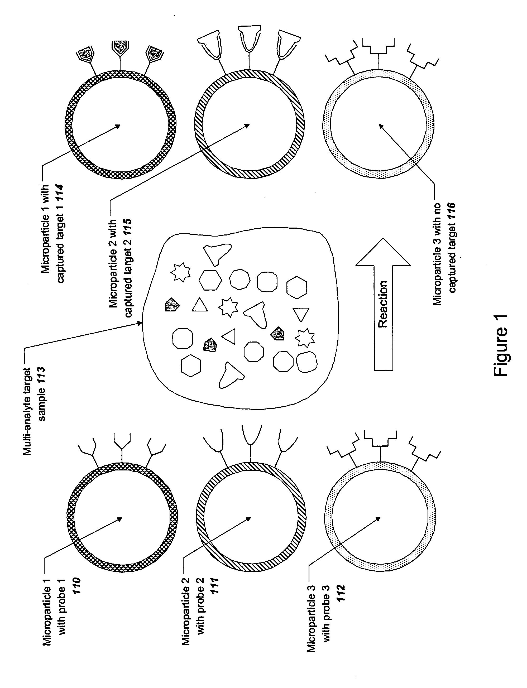
a microparticle and microparticle technology, applied in the field of microparticle-based measurement methods and systems, can solve the problems of slow diffusion of analytes to and on the surface, inability to efficiently control the binding kinetics of microarrays, and inability to cover relatively large diffusion distances of analytes,

Inactive Publication Date: 2005-12-22
PROBER JAMES +6
View PDF26 Cites 61 Cited by
  • Summary
  • Abstract
  • Description
  • Claims
  • Application Information

AI Technical Summary

Benefits of technology

[0281] A significant advantage of the present invention is the potential elimination of binding-related reporter groups in a particle-based assay. Some non-labeled binding methods have been developed for fixed arrays and on other fixed surfaces (for example using surface plasmon resonance in a planar biosensor according to Larsson, A. and Persson, B., “Method for nucleic acid analysis”, U.S. Pat. No. 6,207,381 and Lyon, L. A. et al., “An improved surface plasmon resonance imaging apparatus”, Rev. Scientific Instruments 70, 2076-2081 (1999); Thiel, A. J. et al., “In situ surface plasmon resonance imaging detection of DNA hybridization to oligonucleotide arrays on gold surfaces”, Anal. Chem. 69, 4948-4956 (1997)). However, no such label-free methods exist for particle-based assays. Methods described in the literature relating to particle-based assays, fluorophores, chromophores, nanoparticles, or other reporter groups are either bound to the target or associated in some way with the binding event. A typical measurement is thus the amount of reporter bound to the particle by its association with the target. Before the measurement is made, the excess unbound reporter must be washed away to eliminate high background readings. This takes time and eliminates the opportunity for dynamic measurements, since essentially only an end point is detected.
[0282] In the present invention, since only bound material is detected by means of wavelength shifts in the scattered light spectrum, the presence of unbound targets does not interfere with the measurement in any way. A reporter group is not required for this invention; however, a species associated with the target could still be used to increase assay sensitivity by enhancing the perturbation of refractive index near the particle surface upon binding. Such a signal amplification means would preferably be a small, dielectric particle attached to the analyte, for example a titanium dioxide or silica nanoparticle. The particle should be small enough not to interfere with binding between probe and target and also small enough not to interfere with the detection of scattered light resonances. Typically such a particle would be several nanometers to tens of nanometers in size.
[0283] Another approach toward signal amplification would be to employ a chemical reaction, such as an enzymatic reaction, antibody / antigen reactions, or in situ nucleic acid amplification methods such as rolling circle amplification. Such a method would be specifically triggered to add mass to the particle surface only when binding of a specific target occurs. Whether or not a signal amplifying species is used, the washing step required in literature methods is made optional and, most importantly, the measurement of binding can still be made in real time during the course of the experiment. This feature of the invention enables an entirely new class of particle-based assay measurements, namely the rapid, massively parallel determination of time-dependent binding on a large population of identifiable microparticles, each carrying on its surface a known capture probe. Those skilled in the art would appreciate the large opportunity for applications of this technology in such diverse areas as drug target screening, proteomics, gene or protein expression analysis, and the like.
[0284] An additional advantage of the invention is that a unified detection method and system may be employed for determining both the particle identity and the degree of binding of an analyte. It should be noted that the identity of a particle is contained in the relative pattern of spectral features and not in the absolute locations of the features. When a target is bound, the relative pattern (i.e. the particle identity) is preserved while the pattern shift is indicative of the degree of analyte binding. The use of a unified detection method results in a simpler overall system with fewer reagents, less hardware, and simplified protocols compared to current methods, resulting in a faster, less costly, and more automatable system.
[0285] The final step to determining the presence and optionally the concentration of a given analyte is the association of a specific probe or capture probe with the microparticle whose scattering spectrum has shifted. As explained previously, in a preferred embodiment of the present invention, this association may be provided by the unique identity of the microparticle as reflected in the pattern of resonant light scattering spectral features. By this method, the binding properties of a complex sample can be determined in a single experiment, including not only which specific targets have bound but also the kinetics of binding under defined conditions. Alternatively, the probe and analyte identity may be determined by other techniques already known in the art, while the presence and optionally the concentration of a given analyte is determined by resonant light scattering, as illustrated in the following Examples. EXAMPLES
[0286] The present invention is further defined in the following Examples. It should be understood that these Examples, while indicating preferred embodiments of the invention, are given by way of illustration only. From the above discussion and these Examples, one skilled in the art can ascertain the essential characteristics of this invention, and without departing from the spirit and scope thereof, can make various changes and modifications of the invention to adapt it to various uses and conditions. General Methods

Problems solved by technology

These “biochip” systems can carry out large numbers of analyses simultaneously, but they suffer from known disadvantages.
For example, microarrays have inherently inefficient binding kinetics.
Because of poor mixing at the surface and the dimensions of a typical biochip, an analyte must cover relatively large diffusion distances to bind to its complementary probe.
This results in slow diffusion of analytes to and on the surface, incomplete binding reactions, and substantial lengthening of the protocol.
Additionally, the application and measurement of samples on microarrays is inherently a batch process, not particularly well suited for automation.
Some types of microarrays can be expensive and difficult to customize quickly as the needs of an experiment or assay might require.
Variability across a microarray can lead to degraded reproducibility and precision, requiring in some cases substantial redundancy in the measurements.
Sensitivity and dynamic range are frequently reported to be problematic in the analysis of microarray data.
Also, with fixed microarrays it is not typically possible to recover, sort, post-process, or perform subsequent measurements on the analyte.
The resulting measurement in most microarray systems is thus an end-point measurement; i.e. the microarray is not capable of real-time, continuous measurement of binding between analyte and probe.
As mentioned previously, although non-labeled binding detection has been reported for fixed array systems, the continuing use of external reporter groups in particle-based assays remains a key disadvantage since the associated drawbacks are the same as for fixed arrays.
Because the microparticles can be in free suspension in some applications, it is not possible in those cases to link the identity of the probe to a fixed position, as done in fixed arrays.
Thus, the number of particle-based assays that can be performed in parallel is limited by the number of distinguishable combinations provided by the specific labels employed, e.g. the number of fluorophores, and possibly their relative abundance.
However, use of resonant light scattering spectra for identification of microparticles or for detection in biological and chemical assays is not taught in that disclosure.
However, how such measurements could be made is not taught in that disclosure.
The principal drawbacks to existing labeling techniques include limited multiplicity, i.e., limited combinations of unique identifying features, difficulties in preparing the encoded particles, speed and accuracy of decoding, and, in some cases, cost.

Method used


Image

  • Microparticle-based methods and systems and applications thereof
  • Microparticle-based methods and systems and applications thereof
  • Microparticle-based methods and systems and applications thereof

Examples


example 1

Identification of Individual Glass Microparticles by Resonant Light Scattering

[0290] The purpose of this Example was to demonstrate the identification of individual glass microparticles using resonant light scattering spectra using an optical probe system.

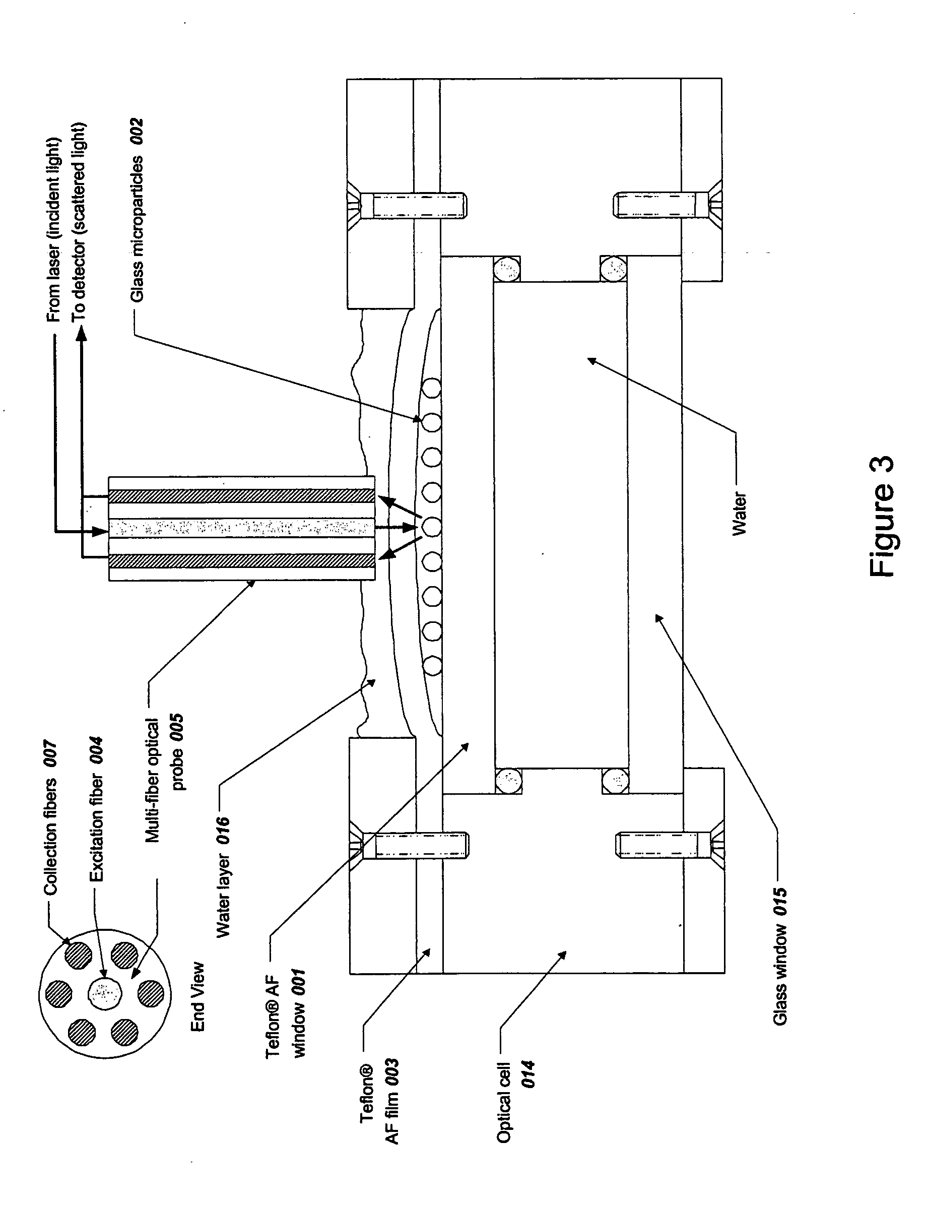
[0291] Spherical glass microparticles of refractive index approximately 1.9 and diameter approximately 35-40 μm (MO-Sci Corp., Rolla, Mo., Product number GL-0175, Lot 7289552-S1) were used without further treatment. Approximately 0.5 g of particles was placed in approximately 10 mL of distilled water and a suspension was created using a magnetic stir bar. A sample of approximately 0.1 mL of this suspension was placed on the top Teflon® AF 2400 (DuPont Co., Wilmington, Del.) window of thickness about 2 mm 001 as shown in FIG. 3. The suspension was optionally covered with a Teflon® AF 2400 cover film (about 0.05 to 0.13 mm thickness) 003 and the glass microparticles 002 were allowed to settle to the upper surface of the top window ...

example 2

Identification of a Multiplicity of Glass Microparticles by Resonant Light Scattering Imaging

[0293] The purpose of this Example was to demonstrate the identification of a multiplicity of glass microparticles by resonant light scattering using a spectral imaging system.

[0294] The spectral imaging system shown in FIG. 7 was used to acquire and process resonant light scattering spectra from multiple glass microspheres simultaneously. The optical cell of FIG. 3 was modified as shown in FIG. 6 by replacing the water underneath the top Teflon® AF 2400 window with an ink absorber solution 018, which consisted of 1 part ink (Higgins Fountain Pen India Ink, Item 46030-723, Sanford Co., Bellwood, Ill.) to 100 parts distilled water. The ink solution served to absorb any incident light that had not interacted with the microspheres, thereby reducing optical noise from scattering and back reflection. The imaging optical cell 019 was loaded with glass microparticles 002 as in Example 1 and place...

example 3

Detection of Binding of Avidin on Biotinylated Microparticles Using Resonant Light Scattering

[0309] The purpose of this Example was to demonstrate detection of avidin binding to biotinylated glass microparticles using resonant light scattering. Amine groups were introduced on the surface of glass microparticles using silane chemistry. Then, the microparticles were biotinylated by reaction with Sulfo-NHS-SS Biotin. Avidin binding to the biotinylated microparticles was detected using resonant light scattering. Reversibility of the binding signal upon cleaving the avidin from the particle was also demonstrated.

[0310] A. Surface Preparation of Microparticles:

[0311] High-refractive index glass microparticles (Mo-Sci Corp., Rolla, Mo., Product number GL-0175, Lot 7289552-S1, refractive index approximately 1.9) were first cleaned by leaching with 0.5 M HNO3 at room temperature for 5 min. The glass particles were then treated with the following series of steps: a deionized water rinse, t...


PUM

PropertyMeasurementUnit
optical wavelengthsaaaaaaaaaa

Abstract

Microparticle-based analytical methods, systems and applications are provided. Specifically, the use of resonant resonant light scattering as an analytical method for determining either or both a particle's identity and the presence and optionally, the concentration of one or more particular target analytes is described. Applications of these microparticle-based methods in biological and chemical assays are also disclosed.

Description

FIELD OF INVENTION [0001] This invention generally relates to methods, systems, and applications for microparticle-based measurements using resonant light scattering, comprising one or more of the following elements: particle identification, determining the identity and degree of analyte binding, and application of these methods in multiplexed biological and chemical assays. BACKGROUND [0002] Advances in bioanalysis are increasingly driven by miniaturization and multiplexing, i.e. the ability to measure many samples simultaneously. The ability to measure more analytes from smaller sample volumes, dictated in many cases by limited sample size, has led to development of miniaturized microfluidics-based sample manipulation systems and novel methods for analysis in micro-scale systems. Examples include a wide variety of existing biological and chemical measurements, for example DNA sequencing, protein analysis, single-nucleotide polymorphism (SNP) analysis, high-speed and high-resolutio...

Claims


Application Information

Patent Timeline
Patent Type & Authority Applications(United States)
IPC IPC(8): C12Q1/68G01N33/53G01N33/537G01N33/543
CPCB82Y5/00B82Y10/00G01N33/54373B82Y20/00G01N33/54346B82Y15/00
Inventor PROBER, JAMESCUI, XIUMINDAM, RUDYHENDRICKSON, EDWINJIANG, XUEPINGPERRY, MICHAELSTEENHOEK, LARRY
Owner PROBER JAMES
Why Eureka
Try Eureka