Method and apparatus for machine guidance at a work site

a work site and machine guidance technology, applied in the direction of machine control, distance measurement, instruments, etc., can solve the problems of affecting the ultimate productivity of handling materials correctly, requiring expensive machine intensive hardware and positioning components, and not allowing multiple machines working on a site to update one another's existing surfa

Inactive Publication Date: 2005-12-22
LEHMAN ALLEN A JR +2
View PDF29 Cites 56 Cited by
  • Summary
  • Abstract
  • Description
  • Claims
  • Application Information

AI Technical Summary

Benefits of technology

[0009] It is another object of the present invention to provide improved machine guidance technologies that will correct deficiencies in coverage, machine knowledge of location and accuracies of work site surfaces amongst multiple machines.
[0010] It is another object of the present invention to provide an apparatus and methodology that will allow multiple machines to work from the same active surface as the data processing

Problems solved by technology

However, existing systems require expensive machine intensive hardware and positioning components, and the requirement to occupy a surface prior to understanding its relative position to a design surface.
This process of the machine creating the DTM based upon its movement over a surface hinders the ultimate productivity of handling the material correctly from the first pass.
This approach does not allow for multiple machines working on a site to update one another's existing surface.
Without the ability to work from the same active surface, multiple machines cannot work together on a single active surface in the same work area.
This severely limit

Method used


Image

  • Method and apparatus for machine guidance at a work site
  • Method and apparatus for machine guidance at a work site
  • Method and apparatus for machine guidance at a work site

Examples


Embodiment Construction

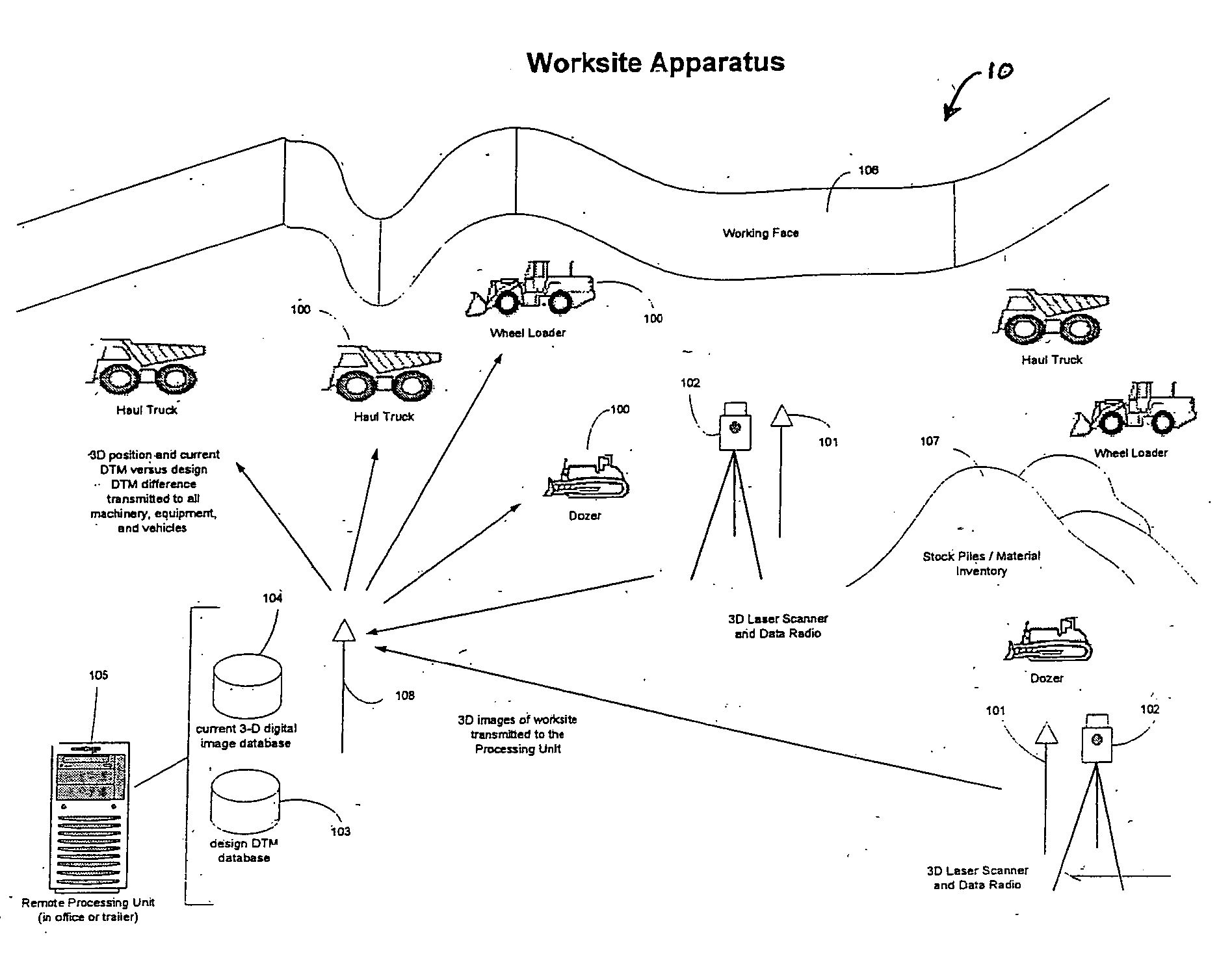
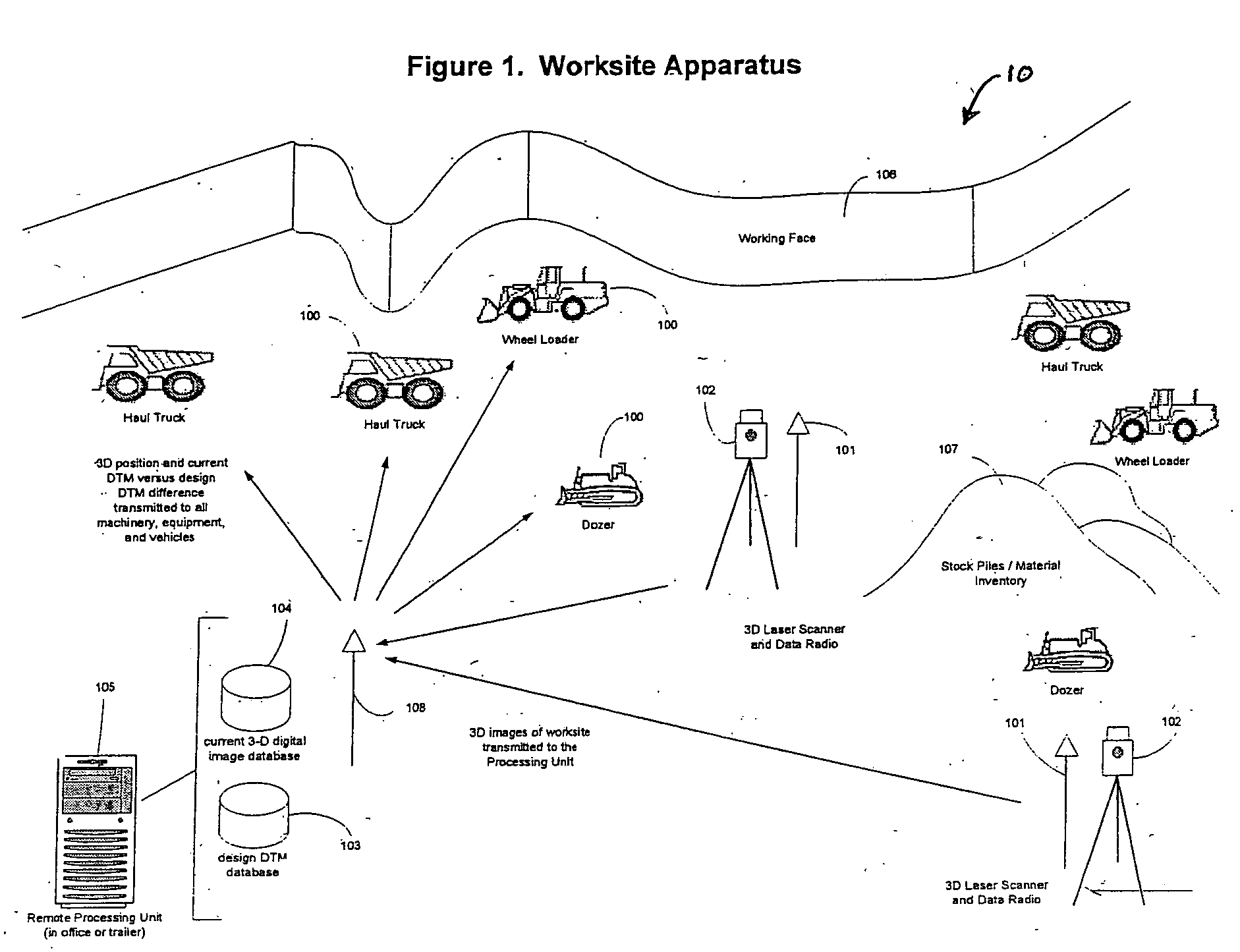
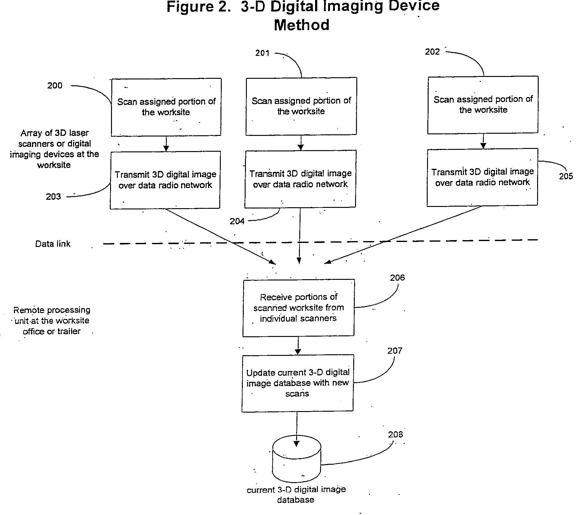
[0012] In accordance with one embodiment of the present invention a system for providing work site guidance for machines and vehicles at the work site is disclosed. The system has at least one imaging device. The imaging device is used for taking three dimensional images of different sections of the entire work site including all machines, vehicles, and potential obstacles. A remote processing unit is coupled to the at least one imaging device. The remote processing unit is used for collecting the three dimensional images and creating a single three dimensional image of the entire work site. A first memory device is coupled to the remote processing unit for storing the three dimensional images of different sections of the work site. A second memory device is coupled to the remote processing unit for storing a design file of the work site. The remote processing unit comparing the single three dimensional image of the entire work site to the design file, the differences between the si...


PUM


Abstract

A method and apparatus for providing machine guidance of all types of earthmoving machinery, other heavy equipment, and work site vehicles. The method and apparatus is applicable to any industrial work site such as a construction site, open pit mine, quarry operation, or landfill. The machinery, equipment, or vehicle is not required to be equipped with a positional receiver of any kind. The position of all machinery, equipment, and vehicles is performed by employing an array of 3D laser scanners (or any 3D digital imaging devices) positioned throughout the work site. 3D images of the work site are transmitted from the laser scanners to a remote processing unit via a data link or network. The processing unit analyzes the images and determines the position of the machinery, equipment and vehicles. The positions are transmitted to the machinery, equipment, and vehicles via the data link or network. The current Digital Terrain Model (DTM) of the work site is captured and stored in real time in the form of a 3-D digital image, as a by-product of scanning the work site and determining the position of the work site machinery, equipment, and vehicles. The remote processing unit compares the current DTM to the work site's design DTM and transmits the difference to the required machinery, equipment, and vehicles for feedback to their operators in real time.

Description

BACKGROUND OF THE INVENTION [0001] 1. Field of the Invention [0002] This invention relates to industrial material moving and, more specifically, to an apparatus and methodology for the guidance, tracking and control of mobile machinery, and related material in an industrial material moving environment. These industrial environments may include mine sites, construction sites, quarries, and any other sites where mobile machinery and material handling are active. Mobile machinery may include any machinery utilized in the process of moving, producing or disposing of material. [0003] 2. Description of the Prior Art [0004] Current machine guidance systems have increased machine productivity a considerable amount. However, existing systems require expensive machine intensive hardware and positioning components, and the requirement to occupy a surface prior to understanding its relative position to a design surface. Current methodologies only allow a machine to gather current surface inform...

Claims


Application Information

Patent Timeline
IPC IPC(8): G05D1/02G06F19/00
CPCG05D1/0236
Inventor LEHMAN, ALLEN A. JR.KNAPP, JAMESHANSEN, EVAN V.
Owner LEHMAN ALLEN A JR
Why Eureka
Try Eureka