System, method, and appartus for deforming and potting coil for disk drive voice coil motor

a voice coil motor and voice coil technology, applied in the field of improved, to achieve the effect of low viscosity, high tg, and low viscosity

Inactive Publication Date: 2005-12-29
HITACHI GLOBAL STORAGE TECH NETHERLANDS BV
View PDF10 Cites 9 Cited by
  • Summary
  • Abstract
  • Description
  • Claims
  • Application Information

AI Technical Summary

Benefits of technology

[0013] One embodiment of a system, method, and apparatus for an improved voice coil motor is described. The principal idea behind the present invention is to fabricate the yoke and coil such that, as wound, the coil is a close fit to the inside perimeter of the yoke, and protrudes above the surface of the yoke by about 50 to 75 microns. With the coil in place in the yoke, it is squashed to fit exactly the inner perimeter and thickness of the yoke. A low viscosity, high Tg adhesive is then applied to the coil. The low viscosity of the adhesive allows capillary action to fill the voids between the wires and bond the coil to the yoke. By potting the coil with a high Tg adhesive, the coil becomes a structural part of the comb. By eliminating the need for a border of adhesive for attachment, the HSA is lighter with less inertia. Since the coil is pressed against the yoke, the heat transfer out of the coil is now metal-to-metal rather than through an adhesive.

Problems solved by technology

This temperature is excessive for the pivot cartridge, thus, the squash and pot procedure must be done prior to installation of the pivot.

Method used


Image

  • System, method, and appartus for deforming and potting coil for disk drive voice coil motor
  • System, method, and appartus for deforming and potting coil for disk drive voice coil motor
  • System, method, and appartus for deforming and potting coil for disk drive voice coil motor

Examples


Embodiment Construction

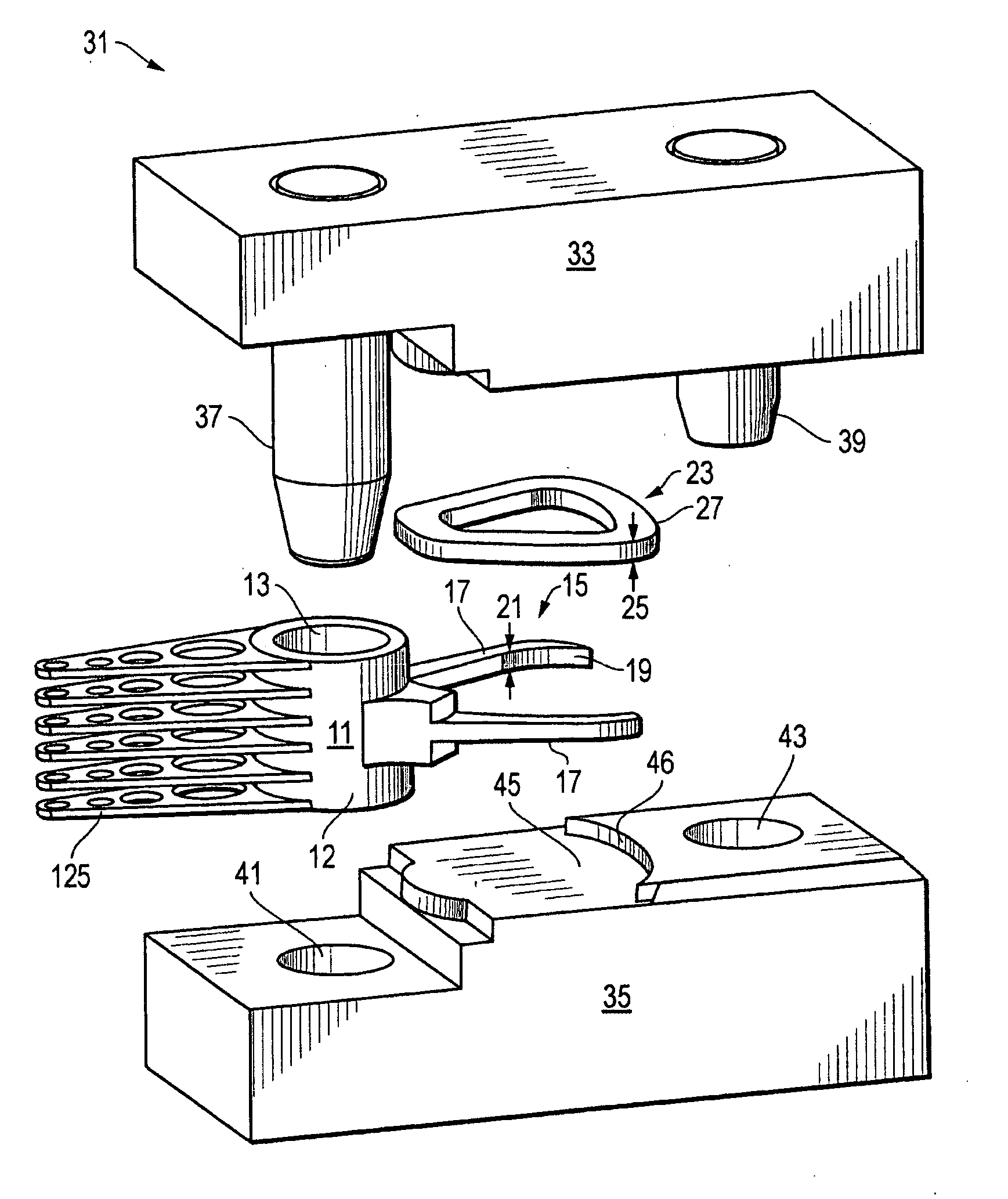
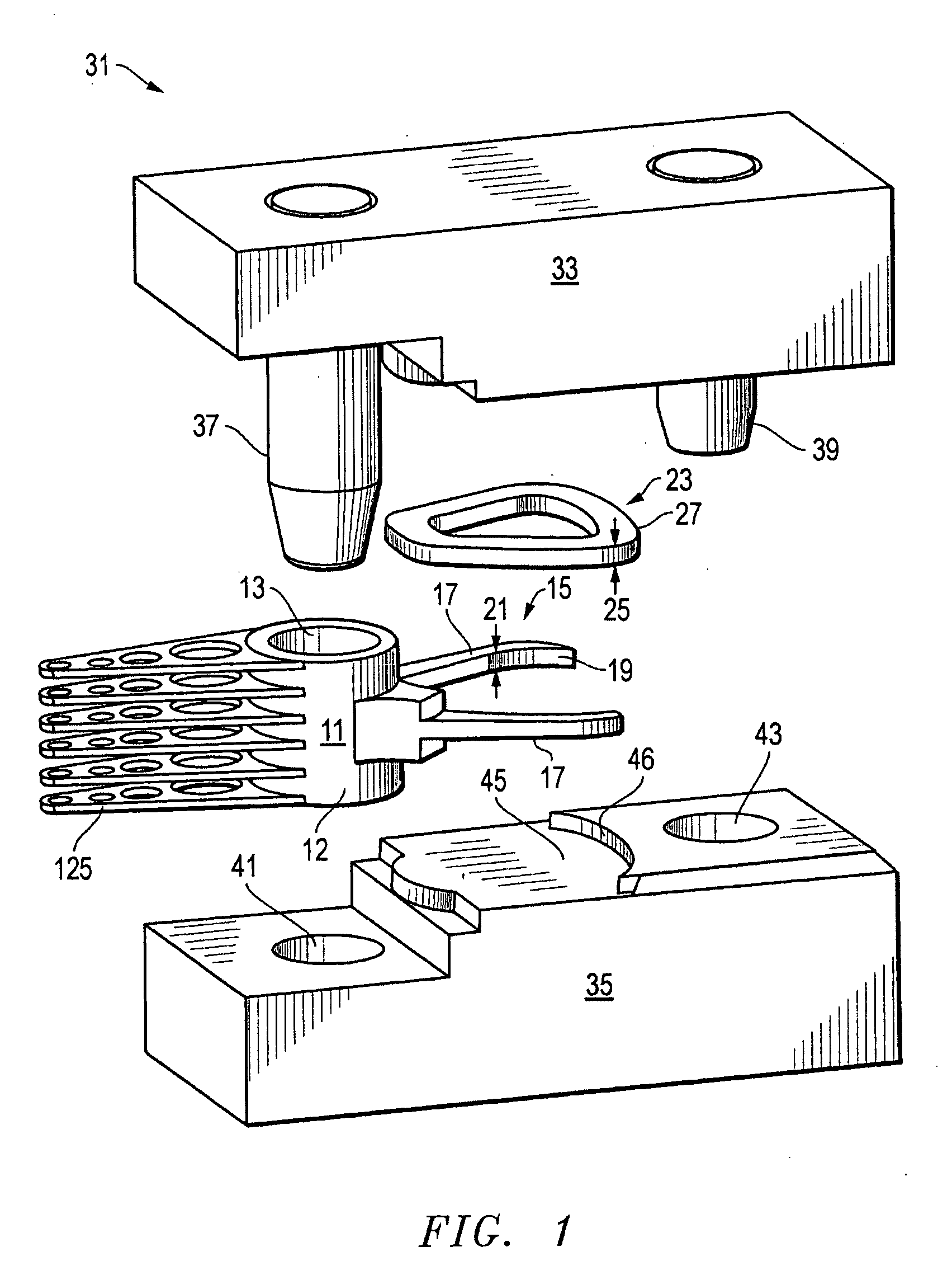
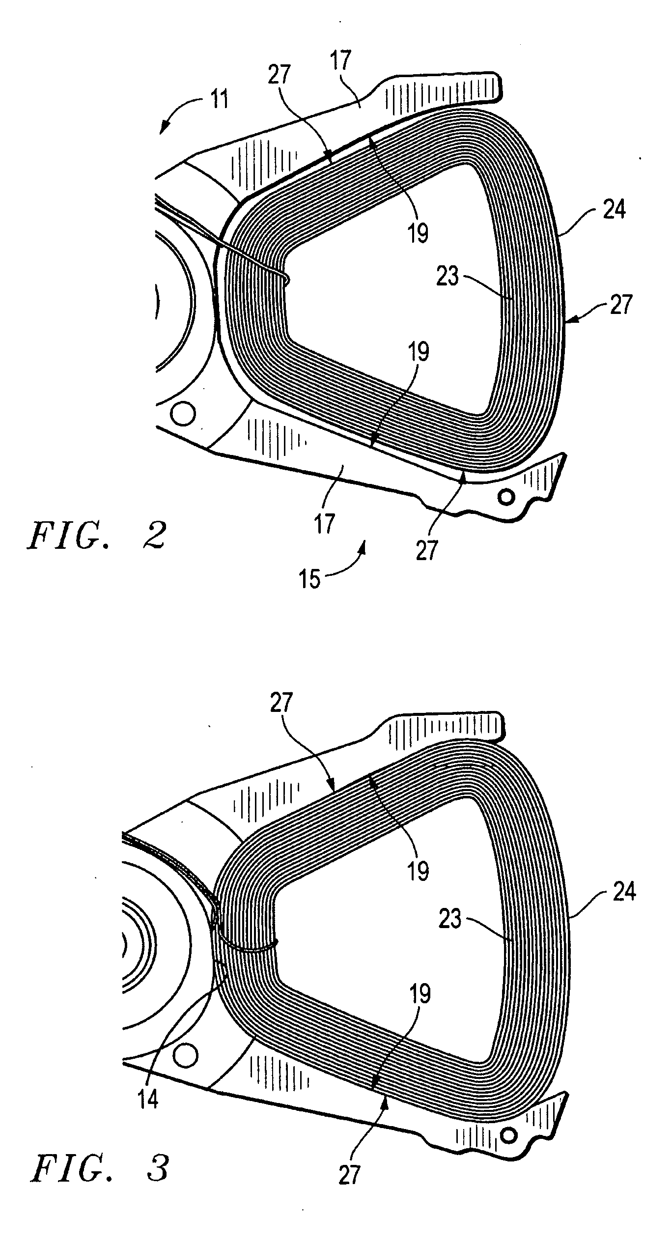
[0029] Referring to FIG. 1, one embodiment of a system, method, and apparatus for fabricating a voice coil motor for a data access storage device is disclosed. The present invention is ideally suited for stiffening an actuator comb and coil assembly. In one embodiment, an actuator comb 11 has a plurality of arms 125, an axial bore 13 for a pivot 123 (FIG. 10) and a yoke 15 opposite the arms 125. The yoke 15 includes a pair of legs 17 that extend from the actuator comb 11 that define an inner perimeter 19 and an axial dimension 21.

[0030] A coil 23 forms a portion of a voice coil motor 133 (FIG. 10) and comprises a wound loop of conductive material, such as copper. The coil 23 has an axial dimension 25 and an outer perimeter 27. The axial dimension 25 of the coil 23 is greater than the axial dimension 21 of the yoke 15. The outer perimeter 27 is shaped complementary to the inner perimeter 19, and the outer perimeter 27 is sized slightly smaller than the inner perimeter 19 (FIGS. 2 an...


PUM

PropertyMeasurementUnit
sizesaaaaaaaaaa
sizesaaaaaaaaaa
widthaaaaaaaaaa

Abstract

A voice coil and actuator yoke assembly is fabricated by deforming the coil to exactly fit the inner perimeter and thickness of the yoke. The comb is placed in a tool that registers the comb with the yoke against the same flat surfaces that will squash the coil. The tooling is closed and placed in an appropriate loading device and the coils are squashed to the precise thickness of the yoke. This eliminates the in-plane tolerances of the current process for bonding a coil into the yoke. The coil perimeter expands as the coil is squashed to form an intimate press fit with the yoke. A low viscosity, high Tg adhesive is then applied to the coil. The low viscosity of the adhesive allows capillary action to fill the voids between the wires and bond the coil to the yoke.

Description

BACKGROUND OF THE INVENTION [0001] 1. Technical Field [0002] The present invention relates in general to an improved voice coil motor and, in particular, to an improved system, method, and apparatus for plastically deforming and potting the voice coil of a voice coil motor for a disk drive. [0003] 2. Description of the Related Art [0004] Data access and storage systems generally comprise one or more storage devices that store data on magnetic or optical storage media. For example, a magnetic storage device is known as a direct access storage device (DASD) or a hard disk drive (HDD) and includes one or more disks and a disk controller to manage local operations concerning the disks. The hard disks themselves are usually made of aluminum alloy or a mixture of glass and ceramic, and are covered with a magnetic coating. Typically, one to five disks are stacked vertically on a common spindle that is turned by a disk drive motor at several thousand revolutions per minute (rpm). Hard disk ...

Claims


Application Information

Patent Timeline
Patent Type & Authority Applications(United States)
IPC IPC(8): G11B5/55H01F7/06H01F7/14H01F27/30H01F41/04H01F41/12H02K15/00H02K41/035
CPCG11B5/5569Y10T29/49071H01F7/14H01F27/306H01F41/04H01F41/127H02K15/00H02K41/0358Y10T29/49025Y10T29/49073Y10T29/53165Y10T29/49066Y10T29/4906Y10T29/49055H01F7/066
Inventor ERPELDING, A. DAVID
Owner HITACHI GLOBAL STORAGE TECH NETHERLANDS BV
Why Eureka
Try Eureka