Methods for optical fiber manufacture

a technology of optical fiber and manufacturing method, which is applied in the field of manufacturing optical fiber, can solve the problems of layer slowing even that process by orders of magnitude, and achieve the effects of reducing the number of geo defect centers produced, reducing the potential for ge defect center formation, and reducing the loss of gexoy

Inactive Publication Date: 2005-12-29
FURAKAWA ELECTRIC NORTH AMERICA INC
View PDF4 Cites 16 Cited by
  • Summary
  • Abstract
  • Description
  • Claims
  • Application Information

AI Technical Summary

Benefits of technology

[0008] To reduce the number of GeO defect centers produced in the MCVD process, we add a buffer layer of undoped silica as the final step in the glass deposition process before beginning the high temperature collapse step. The buffer layer is preferably undoped silica since the consequences of Si sub-oxide defects with respect to long term fiber loss increases are less than those associated with Ge sub-oxide defects. The effect of making the last layer, which is the surface layer on the inside of the tube, of undoped silica is two-fold. First there are fewer Ge dopant atoms in the surface layer that may become oxygen deficient during the collapse, and thus a reduced potential for Ge defect center formation. Second, and more fundamental, the buffer layer prevents direct diffusion of O, O2, and GexOy species out of the deposited Ge-doped silica glass. Ge-atoms may still diffuse out of the Ge-doped region, across the pure silica region, and then out through free surface of the silica buffer layer, with the net effect of altering the refractive index profile (however a buffer layer slows even that process by orders of magnitude due to the inherent slowness of solid-state diffusion). Most significantly, the loss of atomic O from the glass (whether as O, O2, GexOy, SixOy, etc.) can only occur through the free surface at the solid-gas interface. The net result is substantially reduced loss of GexOy, resulting in substantial elimination of the center dip, as well as substantially reduced net loss of oxygen from the Ge-doped region, resulting in significantly fewer germanium sub-oxide defect sites. The method is also effective where this inside surface layer is lightly Ge (or F) doped with respect to the Ge levels in the rest of the core. It will be understood at this point that any reduction in the nominal concentration of Ge dopant species at the glass surface will reduce the number of potential defects attributable to this loss mechanism. With respect to the refractive index dip, the variability of this feature can be removed by the addition of the silica layer and, if even a reproducible dip in the center of the profile is undesirable, most of the silica layer can be etched away in the latter stages of collapse avoiding both the profile dip and the increase in the GeO defects in this region.

Problems solved by technology

Ge-atoms may still diffuse out of the Ge-doped region, across the pure silica region, and then out through free surface of the silica buffer layer, with the net effect of altering the refractive index profile (however a buffer layer slows even that process by orders of magnitude due to the inherent slowness of solid-state diffusion).

Method used


Image

  • Methods for optical fiber manufacture
  • Methods for optical fiber manufacture
  • Methods for optical fiber manufacture

Examples


Embodiment Construction

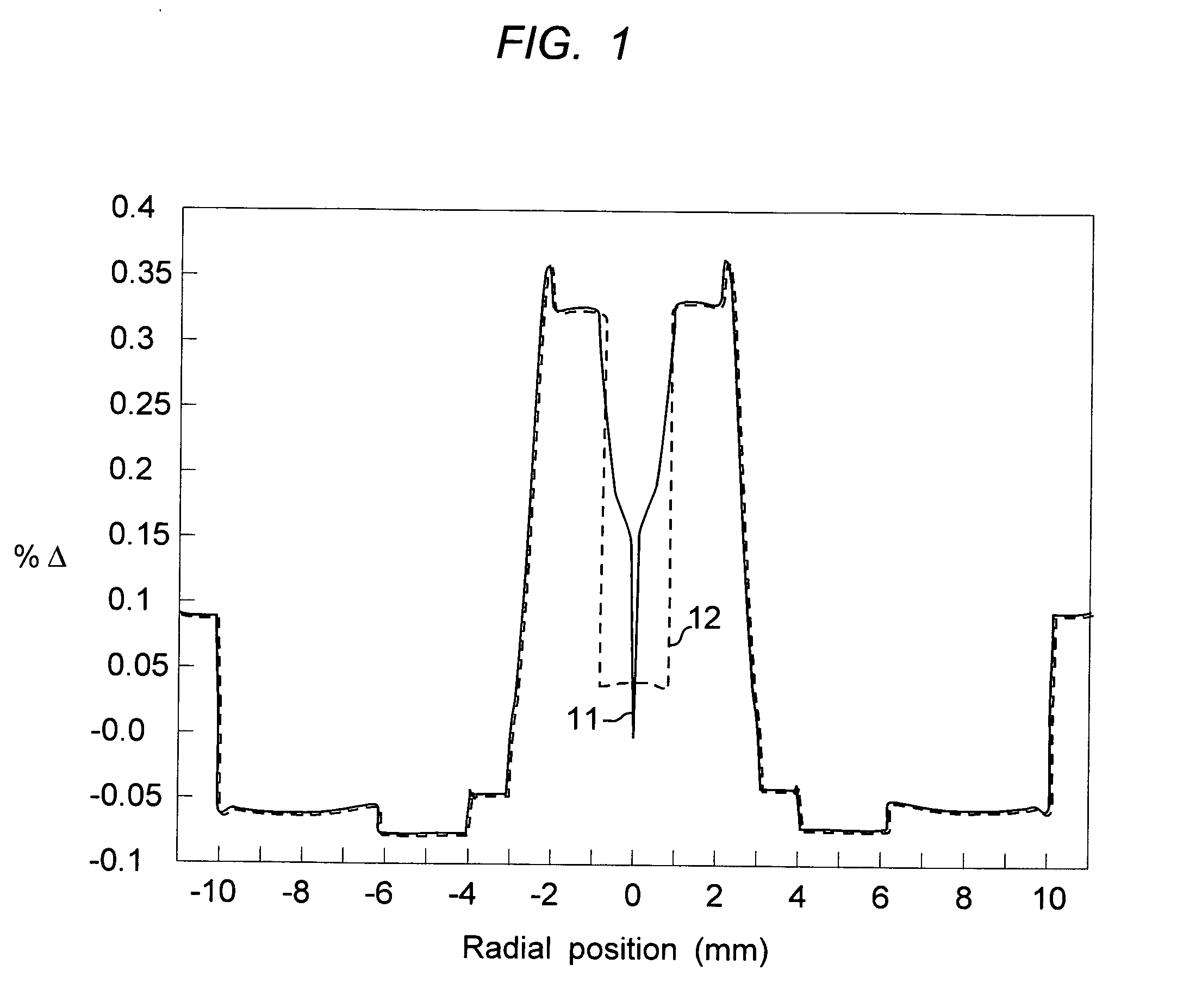
[0019] With reference to FIG. 1, two preform refractive index profiles of a step-index-type design are shown. The central step-index core of the fiber is labeled as 1. The spike structure shows individual MCVD layers which display the characteristic MCVD variation from higher index on the OD of a given layer to lower index on the ID of a given layer. This effect is due to evaporation of germanium from the deposited particle surfaces as each layer is sintered. The effect is most evident for the innermost layer—also the thickest, labeled 2—where the sharp gradation in index is labeled 3, varying from a maximum of approx. 0.325% Δ to a minimum of about 0.225% Δ. The center dip, labeled 4, also known as burnoff, familiar to those skilled in the art, is due to loss of Ge through the inner surface of the hollow MCVD core tube during high temperatures of the collapse step. In the alternate profile, the last deposited layer (4) was replaced by a relatively thick silica layer—an exaggerated ...


PUM

PropertyMeasurementUnit
thicknessaaaaaaaaaa
thicknessaaaaaaaaaa
diameteraaaaaaaaaa

Abstract

The specification describes a method for addressing defects in the center of the core of an optical fiber that are formed during high temperature steps associated with collapsing a hollow core fabricated by the MCVD, PCVD, or OVD methods. These defects form absorption centers and impair the optical transmission properties of the optical fiber. The defects are reduced or eliminated according to the invention by forming a buffer layer as the last deposited layer before collapse. The buffer layer is undoped, or lightly doped, and provides a diffusion barrier to prevent or slow a change in the oxide glass stoichiometry. The result is that fewer dopant and oxygen atoms exit from the core layers through the free surface during collapse, resulting in fewer defects and lower fiber attenuation.

Description

FIELD OF THE INVENTION [0001] This invention relates to methods for manufacturing optical fibers, and to improved optical fiber preform fabrication techniques. BACKGROUND OF THE INVENTION [0002] The Modified Chemical Vapor Deposition (MCVD) method is a widely used approach for the manufacture of optical fibers. In this method, the preparation of the preform from which the optical fiber is drawn involves a glass working lathe, where pure glass or glass soot is formed on the inside of a rotating tube by chemical vapor deposition. Deposition of soot inside the tube allows a high degree of control over the atmosphere of the chemical vapor deposition, and consequently over the composition, purity and optical quality of the preform glass. In particular, the glass making up the central portion or core of the preform should be of the highest purity and optical quality since most of the optical power in the fiber will be carried within this region. Accordingly considerable attention is given...

Claims


Application Information

Patent Timeline
Patent Type & Authority Applications(United States)
IPC IPC(8): C03B37/012C03B37/014C03B37/018
CPCC03B37/01211C03B37/01413C03B2203/22C03B37/01807C03B2201/31C03B37/01473Y02P40/57C03B37/012C03B37/018
Inventor BAYNHAM, GRANTGLODIS, PAUL F.LINGLE, ROBERT JR.
Owner FURAKAWA ELECTRIC NORTH AMERICA INC
Why Eureka
Try Eureka