Joint structure of diverging branch pipe in fuel rail for internal combustion engine, diverging branch pipe and manufacture method of its diverging branch pipe

a technology of internal combustion engine and fuel rail, which is applied in the direction of hose connections, machines/engines, branching pipes, etc., can solve the problems of unsolved problems in the conventional joint structure, deterioration of the fuel injection, and generation of rust, so as to ensure the function of the corrosion prevention face, no deterioration of the fuel, and simple operation

Inactive Publication Date: 2005-12-29
USUI KOKUSAI SANGYO KAISHA LTD
View PDF33 Cites 35 Cited by
  • Summary
  • Abstract
  • Description
  • Claims
  • Application Information

AI Technical Summary

Benefits of technology

[0028] In the joint structure of the present invention, the liquid contact portion of the fuel rail and the diverging branch pipe is formed by stainless steel or the Ni plating film and the Ni base alloy plating film having the corrosion resisting property with respect to the fuel. Therefore, in the fuel rail and the diverging branch pipe, a state perfectly protected from a corrosive environment is secured, and an excellent function on a corrosion preventing face is guaranteed. Further, the diverging branch pipe is constructed by the double pipe formed by the outer pipe and the inner pipe. The inner pipe is constructed by a stainless steel pipe or a pipe body in which a rust preventing film such as Ni or the Ni base alloy film, etc. is formed on the inner circumferential face. The entire liquid contact portion including the seal face with respect to the fuel is covered with the inner pipe. The pressure receiving portion, etc. including the seat face formed by the inner pipe are supported so as to be protected by the outer pipe. Thus, a strong connecting state is maintained in a healthy state, and the inner circumferential face of the inner pipe becomes the seat face. Therefore, the diverging branch pipe sufficiently resists the use of lower gasoline, sour gasoline, DME (dimethyl ether), alcohol, alcohol composite fuel, light oil, hydrogen, etc. Further, since no film of copper exists on the inner circumferential face, no deterioration of the fuel is caused. Further, when the connecting construction is set by interposing the gasket between the joint fitting and the diverging branch pipe, the seat face is formed through the gasket. Therefore, a more excellent airtight property is secured, and each of various kinds of fuels of a high pressure of 15 to 200 MPa can be more reliably sealed. In accordance with the manufacture method of the diverging branch pipe of the present invention, a state perfectly protected from the corrosive environment is secured by a simple operation, and the diverging branch pipe having an excellent function on the corrosion preventing face can be obtained. Therefore, the diverging branch pipe excellent in characteristics for preventing the deterioration of the fuel in advance, etc. can be provided at low cost.

Problems solved by technology

Even when the above liquid contact portion is a narrow portion, the generation of rust becomes a great problem.
Therefore, there is a fear that an abnormality is caused in the injection of the fuel.
Thus, such unsolved problems were left in the conventional joint structure.

Method used


Image

  • Joint structure of diverging branch pipe in fuel rail for internal combustion engine, diverging branch pipe and manufacture method of its diverging branch pipe
  • Joint structure of diverging branch pipe in fuel rail for internal combustion engine, diverging branch pipe and manufacture method of its diverging branch pipe
  • Joint structure of diverging branch pipe in fuel rail for internal combustion engine, diverging branch pipe and manufacture method of its diverging branch pipe

Examples


embodiments

Embodiment 1

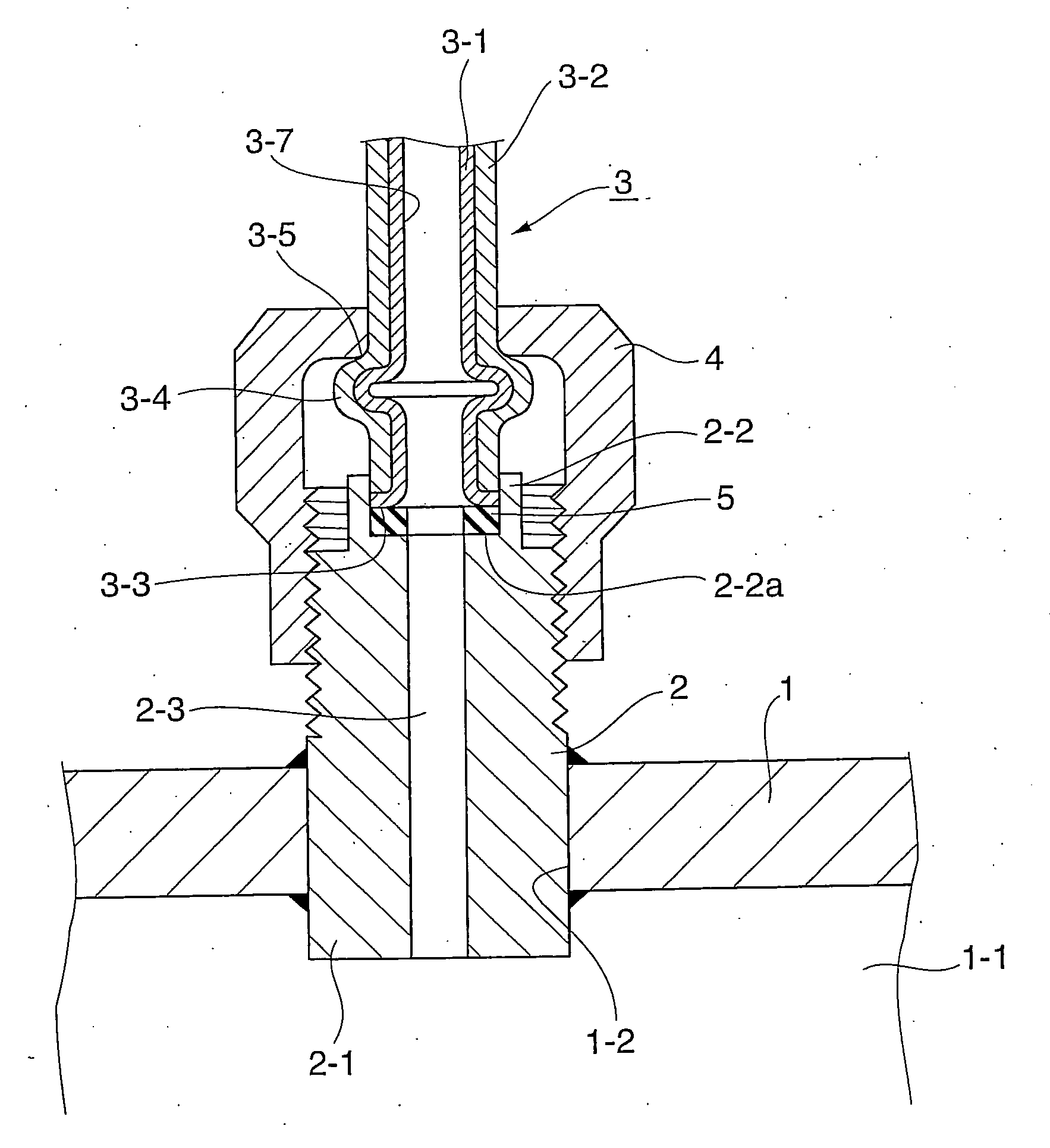
[0052] In the joint structure of a diverging branch pipe in the fuel rail for an internal combustion engine of a first embodiment shown in FIG. 1, a through hole 1-2 communicated with a circulating path 1-1 for fuel is arranged in a circumferential wall portion of a main pipe rail 1. A connecting end portion 2-1 of a joint fitting 2 is mutually joined to this through hole 1-2 in a state in which the tip portion of the connecting end portion 2-1 is fitted and inserted until this tip portion is projected into the circulating path 1-1. Brazing, welding, or diffusion joining, etc. can be arbitrarily selected as a joining means. However, continuous brazing can be efficiently executed by adopting furnace brazing using nickel solder.

[0053] In the joint fitting 2, a connecting seal portion 2-2 of a concave shape in section having a flat face 2-2a perpendicular to the axis of a branching hole of this joint fitting is arranged in an outward opening end portion. A diverging branc...

embodiment 2

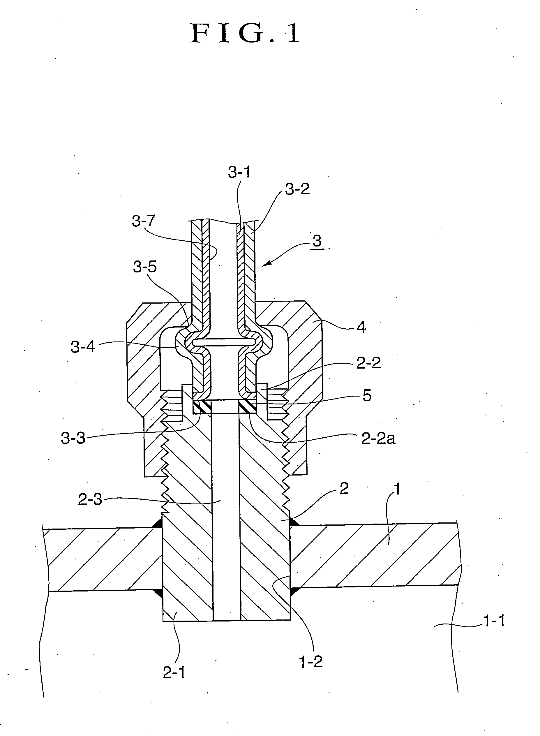
[0056] The joint structure of a diverging branch pipe in the fuel rail for an internal combustion engine of a second embodiment shown in FIG. 2 constitutes a joint structure of the diverging branch pipe in the fuel rail for an internal combustion engine similarly to the first embodiment except that a pressure receiving portion 13-5 with respect to a nut 14 for fastening is formed by arranging a spool 13-4 of the diverging branch pipe 13 of a double pipe structure in only an outer pipe 13-2. In this structure, a connecting end portion 12-1 of a joint fitting 12 is mutually joined to a through hole 11-2 communicated with a circulating path 11-1 of fuel arranged in a circumferential wall portion of a main pipe rail 11 in a state in which the connecting end portion 12-1 is internally projected, fitted and inserted into the through hole 11-2. The diverging branch pipe 13 of the double pipe structure is preferably irregularly fitted to a connecting seal portion 12-2 arranged in an outward...

embodiment 3

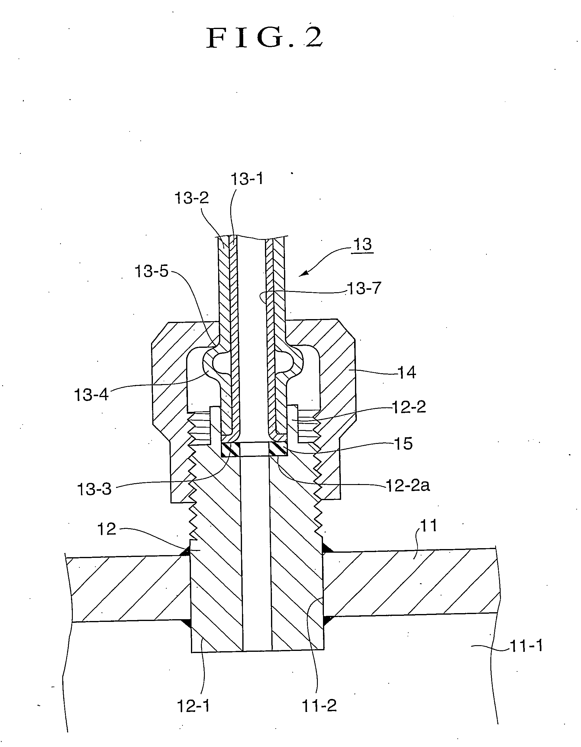
[0058] The joint structure of a diverging branch pipe in the fuel rail for an internal combustion engine of a third embodiment shown in FIG. 3 constitutes a joint structure of the diverging branch pipe in the fuel rail for an internal combustion engine similarly to the first embodiment except that a projection 23-4 is formed at the terminal of the diverging branch pipe 23 of a double pipe structure and is set to a pressure receiving portion 23-5 with respect to a nut for fastening, and a connecting seal portion 22-2 of a concave sectional shape having a flat face 22-2a perpendicular to the axis of a branch hole of a joining fitting 22 arranged in an outward opening end portion of this joint fitting 22 is set to a slanting face widened outwards. Therefore, air tightness with respect to the fuel of high pressure and high temperature is firmly maintained. Further, no exposure portion of an iron system material, etc. exists in a liquid contact portion 23-7 with the fuel, and excellent r...


PUM

PropertyMeasurementUnit
inclination angleaaaaaaaaaa
pressureaaaaaaaaaa
inclination angleaaaaaaaaaa

Abstract

A joint structure connects a diverging branch pipe to a fuel rail for an internal combustion engine. The fuel rail is stainless steel or steel with rust prevention processing on at least the inner face. The diverging branch pipe is a double pipe with inner and outer pipes. The inner pipe has excellent rust preventing ability with respect to fuel on its inner face in comparison with the outer face of the outer pipe. The inner and outer pipes are connected by a nut for fastening through a joint fitting. A connecting seal portion of the diverging branch pipe and the joint fitting has rust preventing ability equal to that of the inner circumferential face of the diverging branch pipe. An entire liquid contact portion, including a seal face of the diverging branch pipe with respect to the fuel is covered with the inner pipe.

Description

TECHNICAL FIELD [0001] The present invention relates to a joint structure of a diverging branch pipe in a fuel rail for an internal combustion engine, and its manufacture method, and more particularly, relates to the joint structure of a diverging branch pipe in the fuel rail (delivery pipe) for a gasoline engine of a direct cylinder interior injection type or a gasoline engine of an intake pipe interior injection type (delivery pipe), or the fuel rail for a diesel engine, the diverging branch pipe, and a manufacture method of this diverging branch pipe. BACKGROUND ART [0002] As the joint structure of the diverging branch pipe in the fuel rail for the internal combustion engine, there is a structure in which a joint fitting (nipple) is mutually joined (brazed, etc.) to a through hole communicated with a circulating path arranged in a circumferential wall portion of a rail main body in a fitting insertion state, and the diverging branch pipe is fastened and connected to this joint fi...

Claims


Application Information

Patent Timeline
Patent Type & Authority Applications(United States)
IPC IPC(8): B21D39/00B21D41/02B21D53/84F02M55/00F02M55/02F02M63/02
CPCF02M55/005F16L41/14F02M55/025F02M55/02F16L41/08
Inventor USUI, MASAYOSHIASADA, KIKUOHASHIMOTO, YASUAKINISHIZAWA, HIROYUKISEINO, IICHIRO
Owner USUI KOKUSAI SANGYO KAISHA LTD
Why Eureka
Try Eureka